
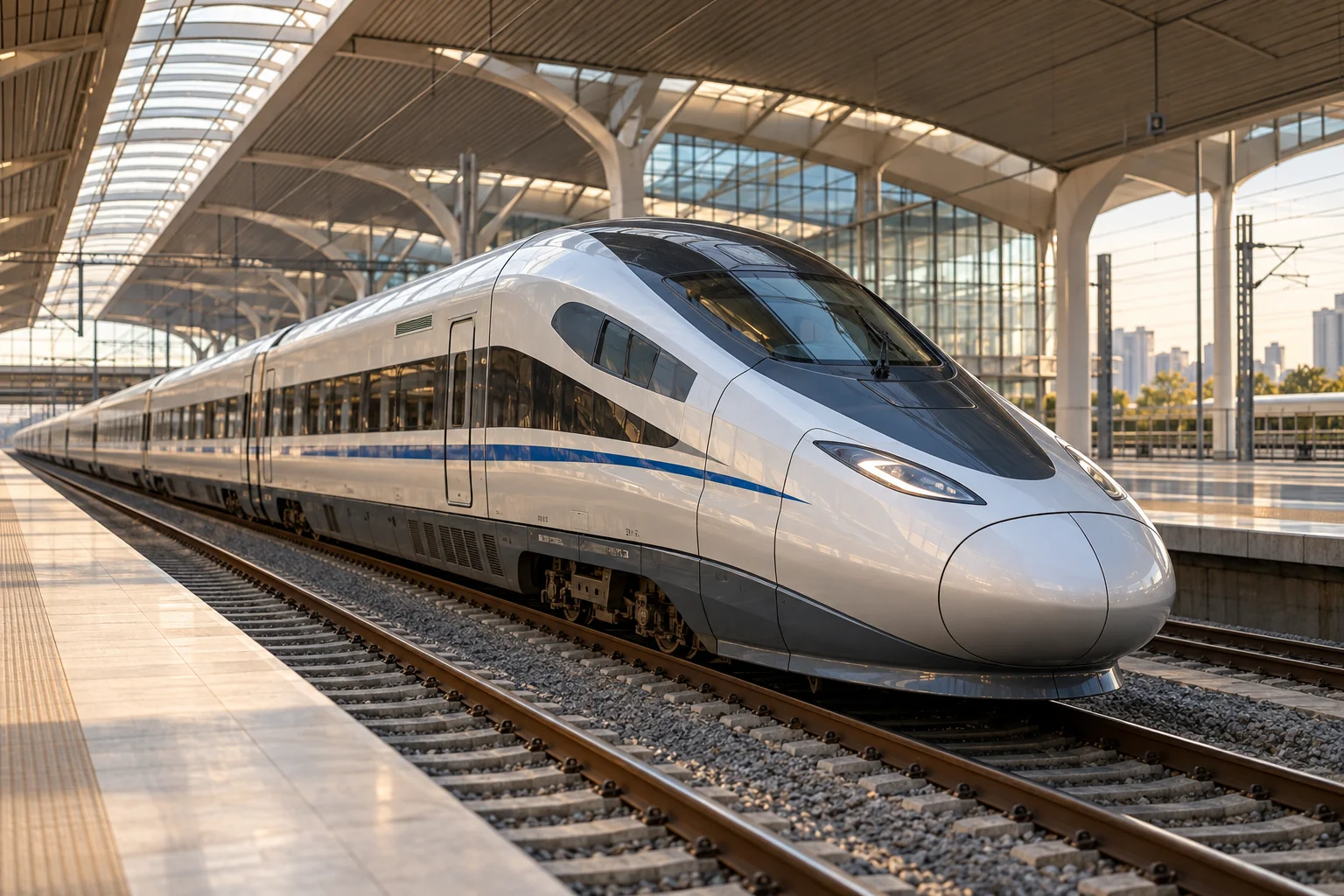
How Railway Trains Work
A vehicle designed together with its path
A railway train is a mechanical transport system whose guidance comes largely from the track. Steel wheels roll on steel rails, allowing heavy loads to move with comparatively low rolling resistance. The price of that efficiency is dependence on a prepared route with controlled curves, gradients, junctions, and clearances. A train may combine a locomotive with unpowered vehicles or distribute traction equipment through several cars. In either arrangement, its behavior depends on the interaction of vehicle, track, braking, power supply, and signaling. Looking only at the locomotive misses much of the machine: the wheelsets and couplings behind it are equally important to moving a useful load.
The wheelset provides guidance
A conventional wheelset has two wheels fixed to a common axle. Their running surfaces are shaped so that lateral movement changes their effective rolling radii, helping the wheelset respond to track curvature. Flanges provide an additional constraint, but a healthy railway does not depend on continuous hard flange contact for all guidance. The contact patches are small and highly stressed, making wheel profiles, rail profiles, materials, and wear important. Tight curves create more demanding interactions than straight track. Wheelsets therefore combine apparently simple rolling motion with complex contact mechanics, and their behavior explains why railway maintenance must consider wheels and rails as a coordinated pair.
Bogies allow long bodies to negotiate curves
Many railway vehicles rest on bogies, sometimes called trucks, which carry wheelsets beneath a larger body. Each bogie can rotate relative to the body as the track curves, avoiding the difficulty of mounting widely separated fixed axles directly under a long vehicle. Primary suspension acts near the axle bearings, while secondary suspension supports the body relative to the bogie. Springs carry weight and permit movement; dampers control oscillation. The bogie frame also carries braking and sometimes traction equipment. Its design must manage vertical loads, longitudinal forces, lateral guidance, vibration, and fatigue while fitting within a restrictive space beneath the passenger compartment or freight platform.
Adhesion sets the available pulling force
Traction motors can produce torque, but the rail contact determines how much of that torque becomes useful train force. If demanded force exceeds available adhesion, a driven wheel can slip. Rain, leaves, contamination, and surface condition can change the available relationship between wheel and rail. Control systems compare wheel behavior and adjust torque; sanding equipment can improve conditions at the contact in appropriate circumstances. Adding motor power alone does not solve an adhesion problem. Distributing driven axles or increasing useful adhesive weight changes the system differently from simply increasing peak output. This is why starting a heavy freight train and sustaining high speed are distinct engineering demands.
Several energy paths can drive the wheels
An electric train collects power from an overhead contact wire or conductor rail, then uses onboard electrical equipment to supply traction motors. A diesel electric locomotive generates electricity onboard and sends it to motors rather than mechanically connecting its engine to every driven axle. Diesel mechanical and hydraulic arrangements exist as well. Motors commonly drive wheelsets through reduction gears, with mounting arrangements designed to accommodate suspension movement. Multiple unit trains distribute this equipment along the formation, potentially improving traction distribution and using passenger carrying space differently from a separate locomotive. Battery and other energy systems change the source, while leaving the final need for controlled wheel torque intact.
Couplings transmit a moving chain of forces
In a locomotive hauled train, the locomotive's tractive effort passes through couplings into the vehicles behind it. Each vehicle contributes mass, rolling resistance, and the effects of gradients and curves. Couplings and their energy absorbing arrangements manage longitudinal forces during starting, stopping, and changes in power. Slack or compliance allows relative movement, but also means forces do not always change uniformly along a long train. The structure of each car must carry those forces through its underframe. An articulated passenger set can use different connection arrangements from a freight train, reflecting different priorities in passenger space, access between cars, modularity, and the way vehicles are assembled or separated.
Braking must act throughout the train
A train cannot rely on braking only at the leading vehicle. Distributed brakes apply force across the formation, using pneumatic commands, electrical commands, or coordinated combinations depending on the system. Friction brakes may act on wheel treads or discs, converting energy into heat. Electric traction equipment can also provide dynamic braking, with energy returned to a receptive electrical supply or dissipated in resistors. The available braking force remains linked to wheel rail adhesion, so wheel slide protection helps manage difficult conditions. Brake design must consider long descents, repeated station stops, emergency demands, and the delay or coordination involved in commanding equipment spread over a considerable distance.
Track and speed reshape the vehicle
A freight wagon and a high speed passenger car face different optimization problems. Freight equipment emphasizes payload, durability, standardized interfaces, and practical loading. Passenger vehicles must also address ride quality, doors, climate control, accessibility, and interior space. At higher speed, aerodynamic drag, pressure changes around tunnels, noise, and dynamic stability become increasingly significant. Unsprung mass affects the forces generated by track irregularities, encouraging careful placement of heavy equipment. The allowable route geometry and quality of track influence the viable vehicle design. A railway vehicle is therefore not a road vehicle that happens to run on rails; its entire structure and dynamics are developed around its guided infrastructure.
The service pattern determines efficiency
A commuter train repeatedly accelerates and brakes, making vehicle mass, station spacing, traction control, and energy recovery important. A long distance train spends more time overcoming resistance at steady speed, while a freight train may devote substantial energy to climbing with a heavy load. Auxiliary systems consume energy even when the train is stationary. Timetabling, route gradients, loading, and available electrical supply affect the overall result alongside motor efficiency. Regenerative energy is most useful when the network or storage system can accept it. Evaluating railway efficiency therefore requires a defined transport task, including passengers or cargo carried, rather than a comparison of isolated locomotive power ratings.
An industrial system with continuing mechanical roots
Railways developed by joining reliable guided tracks with increasingly capable motive power, first through steam and later through diesel and electrical systems. They transformed transport by organizing large flows of people and goods along shared routes. Modern sensors, communications, and control systems improve how this infrastructure is used, but the central mechanical problems remain visible beneath every train: supporting weight, guiding wheelsets, transmitting traction, managing couplings, and removing motion through braking. Their continued importance makes trains a useful bridge between industrial history and current engineering. The technology evolves as an interconnected system, with progress in power equipment constrained and enabled by the track, structures, and vehicles around it.