
How Overhead Cranes Work
Lifting above the working floor
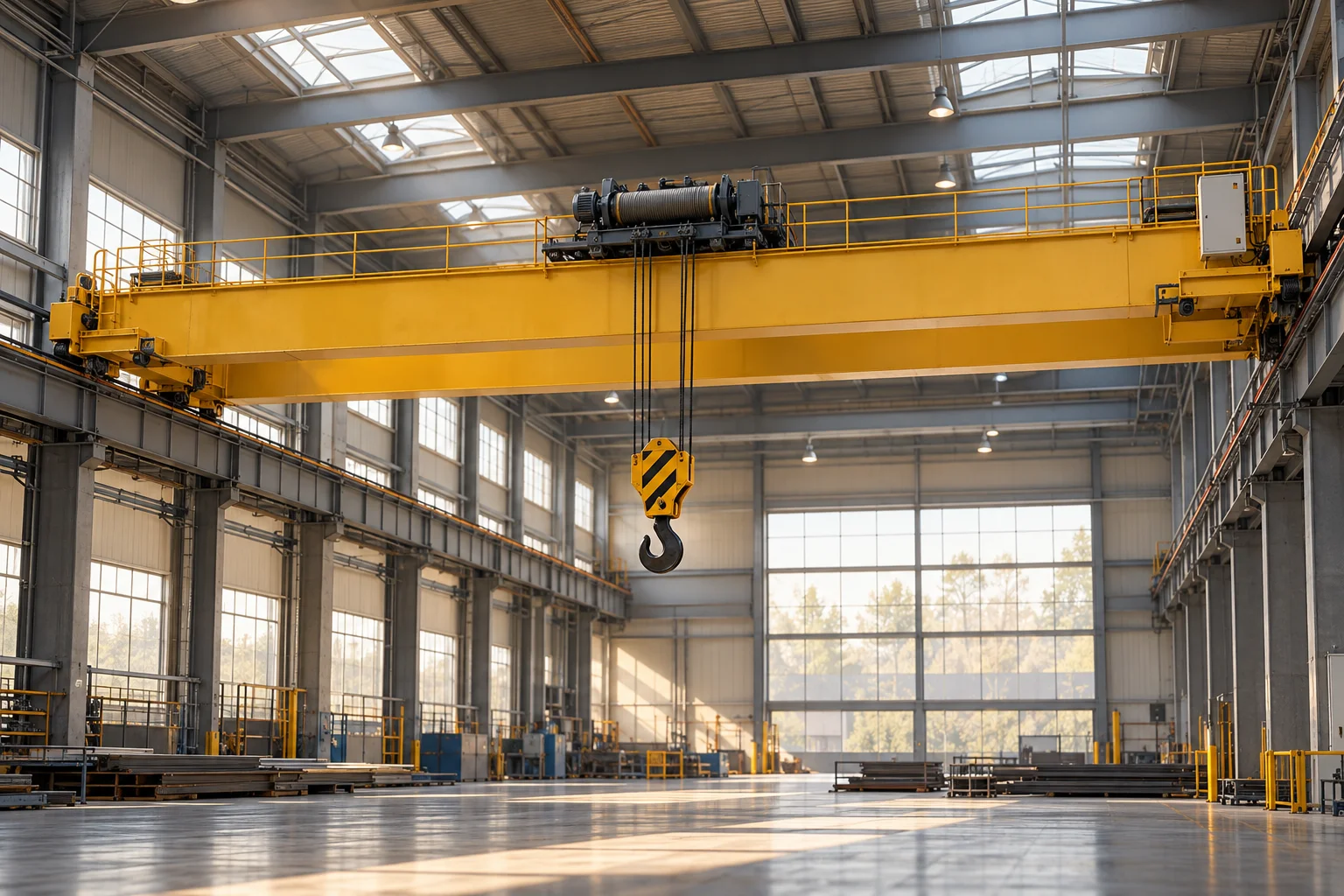
An overhead crane moves a suspended load through a defined working area using equipment supported above that area. In a common bridge crane, a travelling bridge spans two runways, a trolley travels across the bridge, and a hoist raises or lowers the load. Those motions provide useful coverage without requiring the whole lifting machine to occupy the floor beneath it. Factories, maintenance buildings, foundries, and heavy assembly facilities use this arrangement because substantial components can be positioned between workstations while much of the floor remains available for other activity.
The crane is closely tied to its supporting structure. Rails, runway beams, columns, foundations, and building geometry form part of the load path. A powerful hoist alone does not create a complete lifting system. The support must carry vertical forces and respond to horizontal effects from acceleration, braking, alignment, and movement. This makes an overhead crane a useful example of machinery integrated with architecture. Its capabilities depend on the relationship between moving mechanisms, fixed structural elements, the load interface, and the process it serves.
Three motions create a working envelope
Bridge travel moves the lifting assembly along the building or prepared runway. Trolley travel moves the hoist across the bridge. Hoisting changes the vertical position of the suspended load. These motions are commonly treated as separate axes, although their combined effect determines the path of the load. End positions, available headroom, hook approach distances, and obstructions limit the usable space. The region a hook can reach is not necessarily identical to the region in which every load can be handled because the load itself occupies volume and may require additional clearance.
A single-girder and a double-girder bridge organise their structure and trolley support differently. Top-running and under-running arrangements likewise place the moving equipment in different relationships to the runway. These are engineering choices involving capacity, span, available headroom, maintenance access, and structural integration. Konecranes' explanation of overhead crane components identifies the bridge, trolley, and hoist as connected parts rather than interchangeable names. That distinction is important: the hoist supplies vertical movement, while the bridge and trolley provide horizontal coverage through the larger system.
The hoist converts rotation into lifting
A wire-rope hoist uses a driven drum and a reeved rope arrangement to raise and lower the hook block. The motor's rotation passes through transmission components to the drum. Rope winding and the number of supporting rope parts relate drum motion to hook travel. More supporting parts can reduce the tension required in each part for a given suspended load, while increasing the amount of rope movement needed for a given lift. This is another form of mechanical advantage, with corresponding demands on speed, drum capacity, and the arrangement of sheaves.
Chain hoists use a load chain and a suitably shaped driving element instead of a wire rope wound onto a drum. Their application and configuration differ, but both require controlled drive and dependable holding arrangements. Brakes, gearing, bearings, limit devices, and load-facing components work together. Gravity remains present when electrical power is removed, so holding a suspended load is a separate requirement from supplying lifting power. Raising, holding, and controlled lowering must all be understood as designed functions rather than assuming that a motor's ability to rotate explains the whole mechanism.
A suspended load does not follow instantly
A load hanging below a moving trolley behaves partly like a pendulum. When the support accelerates, the suspended mass tends to lag; when movement changes again, the load can swing relative to the hook's support position. Rope length affects the resulting motion. The load's own shape, attachment arrangement, and rotational behaviour can add complexity. This is why a crane's horizontal movement cannot be understood as a rigid platform carrying an object. The load is connected through flexible suspension and responds dynamically to changes in the support's motion.
Controls can shape acceleration and deceleration to reduce unwanted movement, and some systems use additional sensing or calculations to manage sway. These features depend on the crane's configuration and operating assumptions. They do not turn every suspended object into an identical predictable point mass. A long component, a container of liquid, and an irregular assembly can behave differently. The useful engineering question is how the complete load and lifting arrangement respond during a cycle. Smooth positioning results from coordinated motion, suitable control, and an understanding of the physical relationship between support and suspended mass.
The building receives changing forces
Crane bridges bend under their own mass, the trolley, and the lifted load. The position of the trolley changes how those forces are shared between supports. Wheels transmit loads into the runways, and their alignment influences resistance and wear. Horizontal movements introduce additional forces through acceleration, braking, and guidance. Repeated loading also matters: a structure can accumulate fatigue damage even when individual cycles do not resemble a dramatic overload. The intended frequency and severity of service therefore influence design alongside the maximum suspended weight.
The load reaches the hook through slings, lifting fixtures, magnets, grabs, or other specialised interfaces. These attachments influence the load's orientation and the distribution of force. Some cranes serve highly repetitive processes and use dedicated handling equipment; others work with changing assemblies under more varied conditions. The attachment is not an incidental accessory in either case. It completes the connection between the crane's controlled movement and the object being handled. A system description that stops at the hook leaves out the part that determines how the actual load is supported.
Integration makes lifting productive
An overhead crane's value depends on how well it serves the surrounding work. A fabrication shop may need occasional flexible lifting, while a production process may require repeated transfers with carefully defined timing. Controls can range from directly operated interfaces to coordinated automatic cycles. Identification, positioning, interlocks, and communication with other equipment become important when transfers are automated. The available space must also accommodate inspection and maintenance. Components placed high above the floor still need practical access if the system is to remain dependable over its working life.
Overhead cranes connect several fundamental engineering ideas in one visible machine: beams carry loads, wheels guide travel, motors provide power, gearing trades speed for torque, flexible suspension creates dynamics, and controls coordinate motion. Their historical significance lies in bringing heavy positioning capability into industrial buildings and making large assemblies easier to construct, maintain, and move. Understanding them means following the complete chain from the object through its lifting interface, hoist, trolley, bridge, runways, and foundations. The apparently simple act of moving a hook becomes a coordinated relationship between machinery, structure, and industrial organisation.