
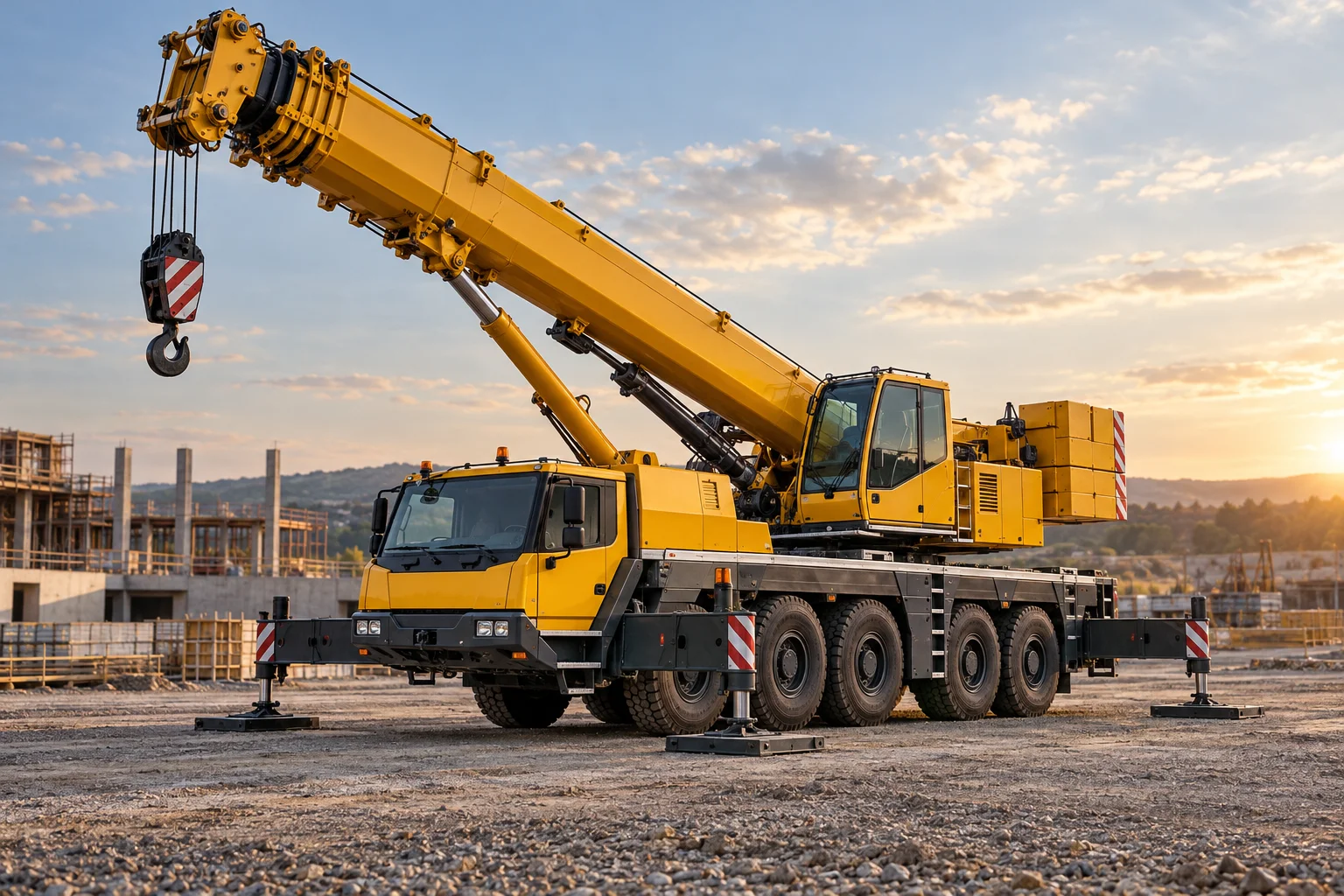
How Mobile Cranes Turn Reach into Controlled Lifting
A crane that travels to the job
A mobile crane places lifting machinery on a carrier that can move between working locations. Its most recognizable feature is a long boom, but the boom is only one element in a system that includes a chassis, rotating upper structure, hoist, ropes, counterweight, controls, and support arrangements. The value of mobility is that lifting capacity can be brought to a site without building a permanent installation. The corresponding challenge is that the crane must transform from a traveling vehicle into a supported lifting structure. Those two roles impose different requirements on weight distribution, dimensions, suspension, steering, and the equipment carried aboard.
The load path
A suspended load acts through the hook and wire rope into the boom and upper structure. From there the forces pass through the slewing bearing, chassis, supports, and ground. The crane's own weight, including its boom and counterweight, also contributes to the structural system. A load farther from the rotation axis creates a greater overturning moment even if its mass remains unchanged. This is why the apparent size of a crane cannot tell an observer what it can lift at a particular radius. Capacity depends on a specified configuration, including reach, support geometry, boom arrangement, and other conditions. The mechanism is fundamentally a problem of force, moment, stiffness, and support.
Extending the boom
Telescopic booms consist of nested structural sections that slide relative to one another. Hydraulic cylinders and associated extension mechanisms move those sections; locks or pins may transfer loads between them in particular designs. Lengthening the boom increases reach while also changing its weight distribution and structural behavior. The sections must resist bending and compression without becoming excessively heavy. Their cross sectional shapes, sliding surfaces, alignment, and manufacturing accuracy all matter. A lattice boom takes another approach, using an open truss structure assembled from sections. Each arrangement represents a different compromise among transportability, assembly, stiffness, weight, and the range of work the crane is intended to perform.
Raising and turning
Changing boom angle alters hook position and load radius. Hydraulic cylinders commonly control this luffing movement on telescopic machines, while other crane types can use rope arrangements. The upper structure rotates on a slewing system, placing the boom over different parts of the supported footprint. Raising, extending, hoisting, and swinging are separate motions that interact through the load's position and the crane's dynamics. A suspended load can also swing like a pendulum when its support accelerates. Coordinating motion is therefore more demanding than bringing a rigidly mounted tool to a target. The control system must allow precise movement while respecting the mechanical limits of the configuration.
Ropes, sheaves, and the hoist
A powered winch winds wire rope onto a drum. The rope may pass through multiple sheaves between the boom head and hook block, sharing load among several rope parts. This reeving changes the relationship between rope pull and hook movement: additional supporting parts can reduce the force required in each part, but the winch must move more rope for a given hook travel. Friction, drum capacity, rope condition, and sheave geometry also influence the system. The hook block itself adds weight to the suspended assembly. Looking at the reeving helps explain why lifting performance involves more than the torque of a winch motor or the strength of one length of cable.
Supporting the lifting structure
Many mobile cranes use outriggers to create a wider support footprint and transfer loads into the ground. Their location, extension, supporting pads, and the strength of the underlying surface all affect the resulting support system. A larger footprint can improve geometric stability, but it cannot compensate for ground that fails under concentrated loads. Carrier suspension and tires may have a different role during travel than during a supported lift. Some machines are designed for particular lifting operations on tires or for moving with a suspended load, but such capability is configuration dependent. There is no sound general rule that treats all mobile cranes as interchangeable in how they are supported.
Traveling machinery
The carrier must bring a heavy, tall, and often unusually long machine through real roads or work areas. Multiple axles distribute mass, while steering arrangements help achieve useful maneuverability. Road speed, turning geometry, ground clearance, transport dimensions, and the ability to carry counterweight or boom equipment all shape the design. All terrain, rough terrain, and truck mounted cranes make different compromises. A machine optimized for highway travel may not have the same working site mobility as one intended for difficult ground. Even before the hook is used, the carrier is an intricate piece of transport engineering, built around the unusual structure it must deliver.
Sensing and informed control
Modern cranes can measure or infer boom geometry, pressures, loads, and other conditions, then present information or limit certain movements. Such systems depend on correct configuration data and calibrated measurements. They support the operation of a physical machine; they do not suspend the laws of mechanics or make an unsuitable setup acceptable. Electronic control can coordinate drives, improve smoothness, and make complex configurations easier to understand. The essential information is contextual rather than a single headline capacity. A meaningful engineering description explains where the load is, how forces reach the ground, and which parts of the structure or stability envelope constrain the movement.
From lifting appliance to adaptable system
Mobile cranes connect long established principles of hoisting with hydraulic actuation, vehicle design, high strength structures, and electronic supervision. Their development has expanded the range of places where large components can be assembled or maintained. Bridges, factories, energy installations, and infrastructure all benefit from moving heavy parts through a controlled three dimensional path. The most revealing way to study a crane is to trace both the suspended load and its reactions through the complete system. Reach has value only when it is accompanied by an appropriate support structure and controllable motion. That relationship gives the mobile crane its distinctive combination of flexibility, complexity, and engineering discipline.
Precision at the end of a flexible system
The hook is connected to the operator through several flexible elements. Wire ropes stretch under tension, a long boom deflects, support structures deform, and the suspended load responds with its own oscillations. None of these effects necessarily indicates a fault; they are part of real structures carrying force. Their consequences become especially visible when placing a component accurately. A change in load can alter boom deflection and therefore hook position even if no drive has been commanded to move. Engineers account for these relationships through structural analysis, control behavior, and configuration specific information. A crane should consequently be imagined as an elastic system with moving masses, not as a perfectly rigid drawing whose hook always stays at its geometric intersection.