
How Does an Industrial Laser Cutter Work?
Light performs a material separation process
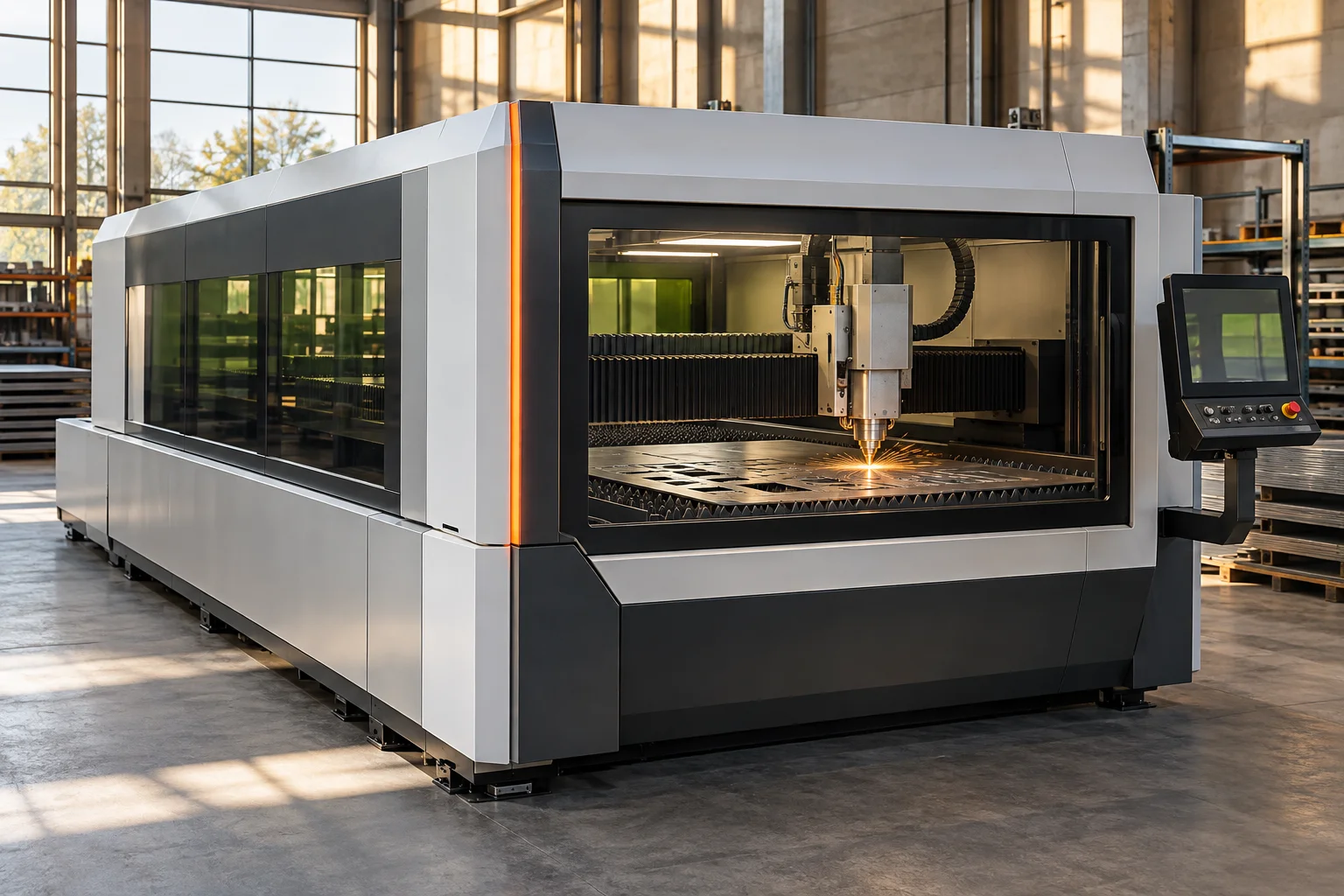
An industrial laser cutter guides concentrated optical energy along a planned path to separate material. For sheet metal, the process usually involves heating a very small region and removing material from the resulting cut. The machine must coordinate the beam, the cutting head, the workpiece, gas flow, and motion. The visible bright spot is only the local expression of that larger system.
The category includes different laser sources, material types, and cutting arrangements. A flatbed sheet metal machine differs from a tube cutter or a small nonmetal engraving system. Even within metal cutting, process behavior changes with material and thickness. The useful starting point is therefore the energy path: where the light is generated, how it reaches the work, how it is focused, and how the heated material leaves the cut.
Producing and delivering the beam
The laser source supplies light with characteristics suited to the intended process. Industrial systems can use different source technologies, including fiber lasers and carbon dioxide lasers. Their optical arrangements and interactions with materials differ. A beam suitable for one task is not automatically ideal for every material simply because its stated power is high.
The delivery system directs energy toward the cutting head. Depending on the technology, this may involve optical fibers, mirrors, and other optical components. The beam must arrive in a usable condition despite the movement of the head and the industrial environment around it. Protection, cooling, and cleanliness matter because small changes in an optical path can influence a concentrated process. The laser source is consequently connected to a complete optical and mechanical system rather than shining directly at a distant sheet without intermediate control.
Focusing creates a localized working region
Optics in the head concentrate the beam near the surface or within the material according to the process design. The focused region has a finite size and depth, not an infinitely thin mathematical point. The position of that region relative to the workpiece affects how energy is distributed through the cut. Changes in thickness, surface condition, and material response alter the process requirements.
Maintaining the head's relationship to the sheet is therefore important. A sheet can be slightly distorted, and thermal effects can change its shape during cutting. Height sensing and controlled movement help the head follow the intended separation from the surface. The arrangement must also keep its nozzle and optical elements compatible with gas flow and the evolving cut. A small region of focused light depends on a much larger mechanism preserving several physical relationships around it.
Gas flow and heat determine the kerf
In many metal cutting processes, a gas jet helps move molten material out of the narrow opening, or kerf. Different gases can play different roles. Some processes use a gas that participates chemically, while others use a gas chosen to limit particular reactions. The material and desired edge condition help determine the relevant method. This is a process distinction, not a simple ranking of one gas as universally superior.
The energy delivered, the speed of motion, the gas behavior, and the material properties together determine whether a continuous cut forms. The removed material must find a path out while the beam advances. The edge records this interaction through its shape, surface condition, and heat affected region. More laser power alone cannot guarantee a better result if the rest of the process does not provide suitable conditions for material removal.
Motion turns a concentrated process into a shape
A motion system carries the head, the workpiece, or both along programmed paths. Motors, guides, transmissions, encoders, and control algorithms establish the relative movement. As with other numerically controlled machines, the mechanism cannot change velocity or direction without considering inertia and available drive force. Curves and corners consequently place different demands on both motion planning and the cutting process.
The thermal interaction is also sensitive to time. A path that slows sharply can deliver a different amount of energy per length unless the process responds appropriately. Controllers therefore coordinate source behavior and travel instead of treating them as unrelated functions. The final outline is produced by a sequence of local events, each influenced by what happened immediately before it. That is why a laser cutter is better understood as a controlled manufacturing process than as a moving pen drawing with light.
Work support and process preparation
The sheet needs support while allowing the cut and removed material to pass through the working zone. Cutting tables may use slats, pallets, or other structures that balance support with access. Finished components and remaining skeleton material must then be handled. Automated loading and unloading can connect the cutter to a larger production flow, especially where repeated sheet processing is required.
Path planning includes more than following the outside of each component. The arrangement of parts on a sheet affects material use, handling, and the sequence of cuts. The machine also needs a way to establish a starting opening before following a contour. Small features, narrow sections, and neighboring cuts can behave differently from an isolated straight line. These practical details reveal how geometry, heat, and logistics influence what appears at first to be a purely digital task.
Optical precision still requires a complete machine
Laser cutting avoids the same continuous tool contact forces present in many conventional cutting processes, but it does not eliminate mechanical demands. The head still has mass, the structure still vibrates, the sheet still moves or distorts, and optical elements still need a controlled environment. Extraction, filtration, cooling, and enclosure design support the process by managing heat, particles, and the working zone.
An attractive edge and an accurate outline also describe different aspects of a part. Dimensional behavior, surface condition, local heat effects, and production consistency may each matter differently to its intended use. The machine's capability cannot be reduced to a single figure for positioning or optical power. It emerges from the optical source, focused interaction, gas delivery, material support, and motion system maintaining an appropriate relationship through the full path.
From flexible outlines to production systems
The appeal of laser cutting is the ability to change a programmed shape without replacing a dedicated physical cutting die. That flexibility connects digital design to physical manufacturing. It does not remove the need to understand material response or the later operations a component must undergo. A laser cut blank may still need bending, joining, finishing, or inspection.
To read a laser cutter, trace four paths together: light from source to focus, gas through the nozzle and kerf, motion along the component outline, and material through the production cell. Each path explains a different part of the machine. Their coordination makes it possible to turn a small, localized interaction into a large family of useful objects. The sophistication lies less in the brightness of the cutting point than in preserving those relationships consistently across many different shapes.
Part layout adds a further layer of engineering. Closely packed shapes can reduce unused sheet area, yet the sequence of cuts influences heat accumulation and the stability of small remnants. Designers and programmers therefore consider material use together with thermal behaviour and reliable part separation. A visually efficient nesting pattern is only one part of an efficient manufacturing process.