
How Does a Mechanized Irrigation System Work?
A moving distribution network
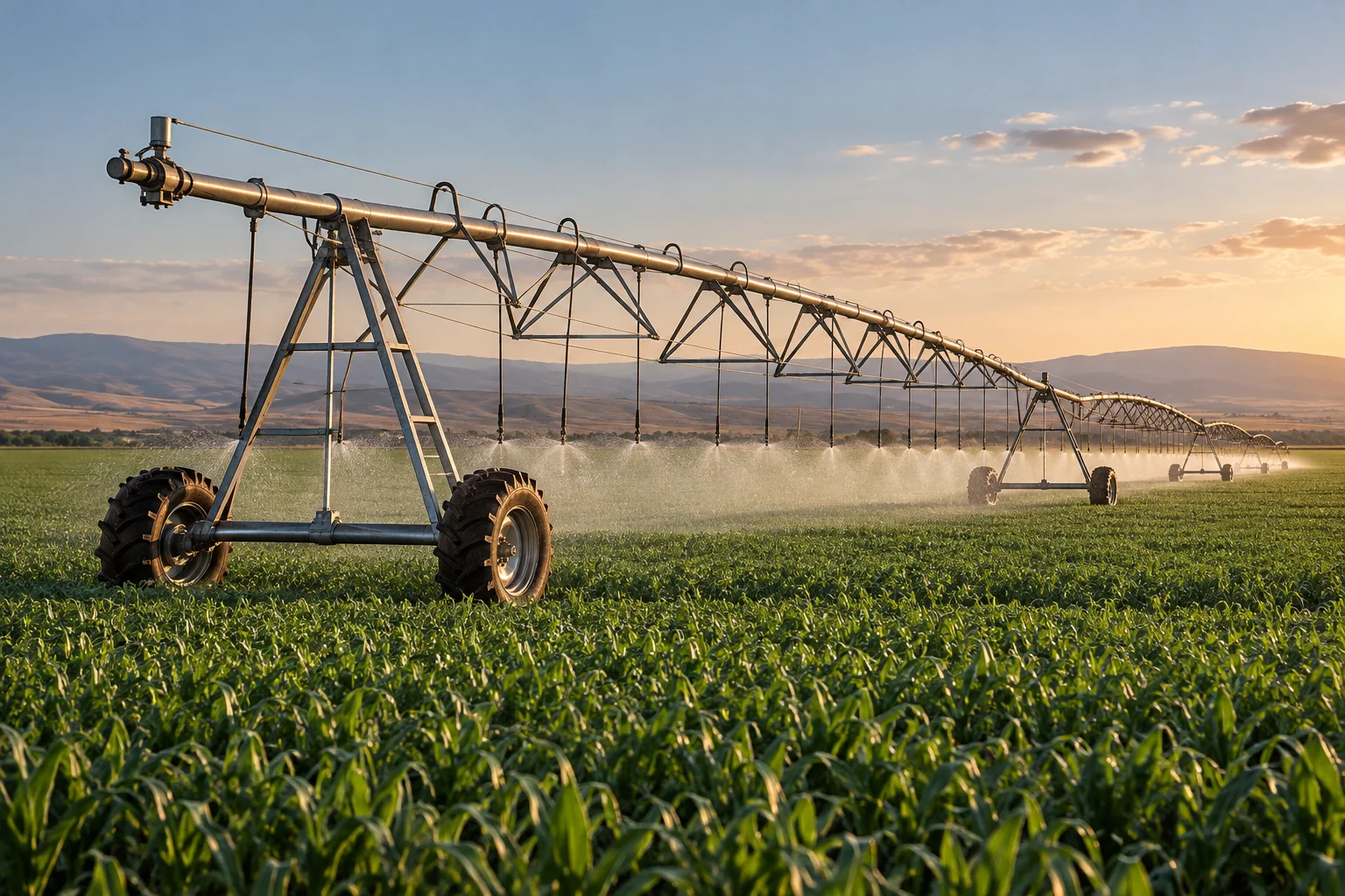
Mechanized irrigation carries water from a supply to a field and distributes it through a controlled pattern. A center pivot is its most recognizable form: a long line of pipe and sprinklers rotates around a fixed point on wheeled towers. A lateral move system travels across the field instead of turning around one center. Both combine fluid transport with slow, coordinated mechanical movement.
The machine is often seen from a distance, where its structure looks almost effortless. Up close, it is a chain of pressure changes, structural loads, gear reductions, electrical controls, and water outlets. Its purpose is not simply to make water travel farther. It must distribute water while moving over uneven ground, carrying its own changing loads, and maintaining an appropriate relationship between local discharge and the area covered.
Energy begins at the water source
Water may come from a reservoir, channel, well, or another supply. A pump adds energy where needed to move that water through pipes, overcome elevation differences, and provide the pressure required by distribution components. The required pumping work depends on the complete route, including frictional losses and the flow demanded by the irrigation equipment.
A pressure at one location is not the same as the pressure everywhere. Water loses energy along pipes and fittings, and a rise in ground elevation changes the pressure available at a distant outlet. Designers therefore consider the supply and the moving machine together. A bigger pump is not automatically a better solution: excess pressure can increase energy use and create a need for regulation. The aim is a suitable operating relationship between source, pipeline, and outlets rather than the largest available flow in isolation.
Structure spans between towers
The main pipeline is supported by a series of wheeled towers and trussed spans. The truss allows a relatively slender pipe assembly to cross substantial distances without behaving like a freely sagging hose. It carries pipe mass, water mass, sprinkler hardware, and loads created by wind and movement. Joints between spans allow the line to accommodate changes in terrain and alignment.
Each tower acts as a small vehicle supporting a shared structure. A motor and reduction drive move its wheels slowly, while the connected spans constrain how it can travel. The towers cannot be treated as independent carts because excessive misalignment would load the pipe and truss system. Flexibility is necessary, but uncontrolled flexibility would defeat the machine's purpose. The design balances articulation, stiffness, weight, and the ability to carry water without creating unacceptable stresses along the moving line.
Coordinated motion creates the covered area
In a center pivot, a tower farther from the fixed point must travel a longer distance during one complete rotation. The towers therefore need different average travel speeds even though they share the same angular progress around the field. Alignment controls coordinate their movements so that the spans remain within their intended geometry. The outer part of the machine governs much of the overall pace.
This geometry also affects water distribution. Outer outlets sweep a greater area than inner outlets in the same time. A suitable sprinkler package must account for that difference rather than supply identical quantities everywhere along the pipe. A lateral move machine has a different area relationship because its outlets travel approximately parallel paths. Seeing irrigation as a moving pattern over the ground explains why its mechanical arrangement and its fluid design cannot be developed separately.
Outlets turn pipe flow into a ground pattern
Sprinklers, spray plates, drop hoses, and related outlet arrangements distribute water from the pipeline. The geometry and local pressure influence how the water leaves each outlet and how it is spread. Pressure regulators can help reduce the effect of changing supply or elevation at individual positions, within their design limits. The resulting pattern still interacts with wind, the crop, and the soil surface.
A visible spray does not directly reveal the amount stored in the root zone. Some water may evaporate, move beyond the intended area, run across the surface, or pass downward differently through the soil. These outcomes involve agronomy and hydrology as well as mechanics. The engineering introduction begins with the controllable part: how discharge, outlet spacing, movement, and local pressure create an application pattern. That distinction prevents confusing a visually impressive spray with a complete measure of useful irrigation.
Control adds information to slow machinery
A controller can schedule movement, monitor pressure, report alignment conditions, and coordinate different operating sections. Position sensing may help the system vary its behavior across different parts of the field. Variable rate irrigation can involve changes in speed or changes to selected outlets, depending on the equipment. Slower travel generally means a given area remains under the distribution pattern for longer, while outlet control changes where water is released.
Information does not remove the physical limits. A commanded change takes time to move through valves, flowing water, and the machine's travel. Ground conditions can also alter wheel behavior. A control display represents the intended process; the real distribution emerges from the interaction of water, structure, drives, and terrain. Understanding those delays and interactions is more useful than imagining that a digital map transfers instantly and perfectly onto every patch of soil.
A system shaped by the field
Irrigation equipment must fit field shape, topography, water availability, crops, and existing infrastructure. A circular coverage pattern can leave corners that a rectangular field possesses. Corner systems and other extensions address some layouts, while lateral move machines suit different arrangements. No single geometry is inherently correct for every farm, because each additional mechanism changes cost, complexity, and movement requirements.
The wider historical significance is the combination of pumping with repeatable distribution. Earlier irrigation often depended on channels, gravity, or movable labor intensive equipment. Mechanized systems organized the water path and the equipment path into a coordinated operation. Follow water from source to pump, along the trussed pipeline, and through the outlets. Then follow each tower across the ground. The machine becomes a clear example of engineering that is simultaneously hydraulic, structural, electrical, and geographical.
Reading the machine across scales
The same irrigation installation can be examined at the scale of a nozzle, a tower, a span, or a complete field. Each scale reveals a different problem. A nozzle controls a local discharge pattern. A tower converts motor torque into travel. A span carries water while accommodating movement. The full installation translates these local actions into coverage across land. None of these views alone provides a complete explanation.
The connection among scales also explains why modifications have consequences elsewhere. Changing outlet demand alters pipe flow. Changing travel behavior changes application duration. Changing structural mass changes the loads that drives and towers must carry. Treating these as connected decisions is more useful than attributing performance to a single controller or pump. Mechanized irrigation shows how a large machine can achieve a seemingly simple result through many coordinated components distributed over an unusually extensive working space.