
Injection moulding machines
Melting, injection & clamping
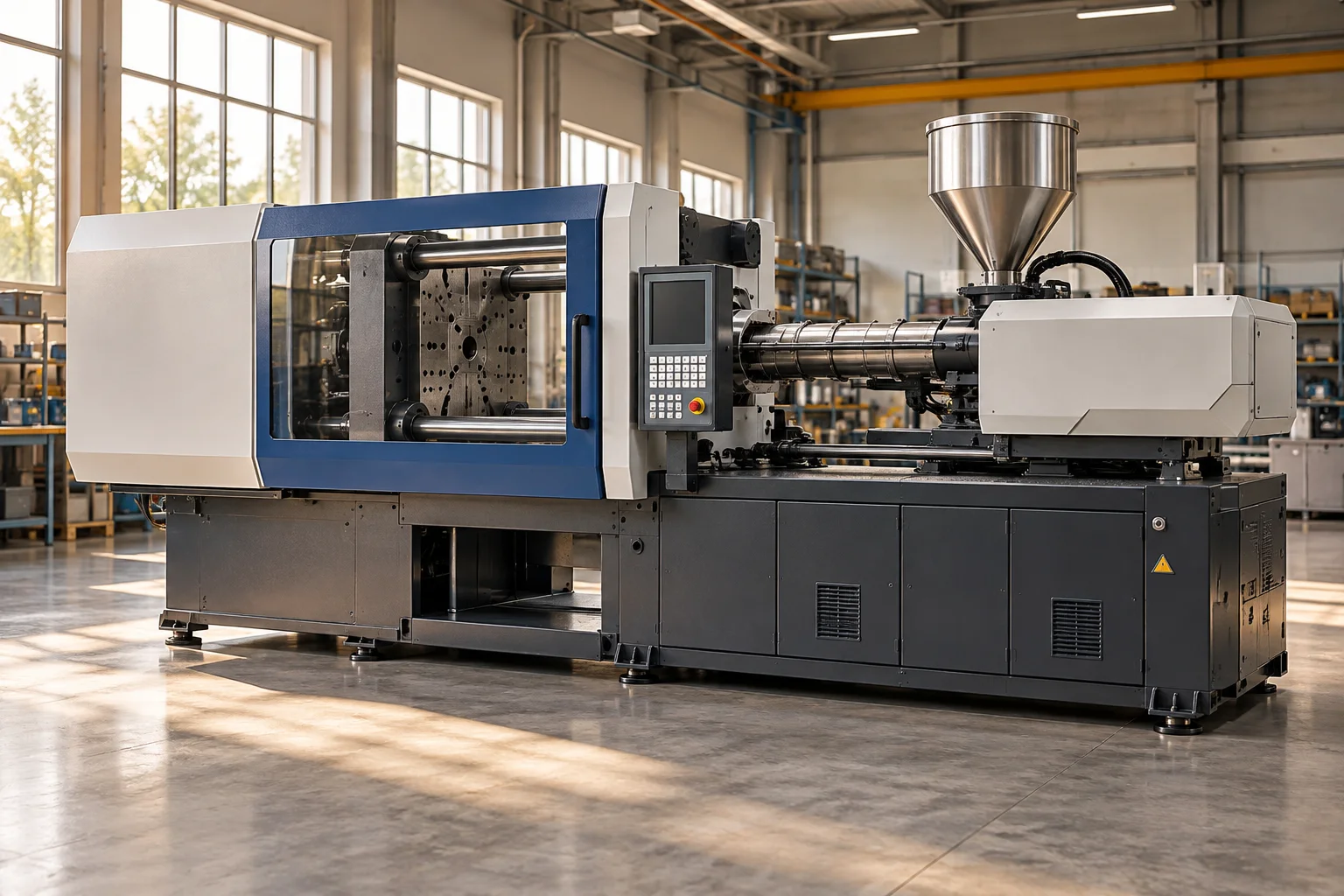
How Does an Injection Moulding Machine Work?
Repeating a shape by controlling material state
An injection moulding machine forms parts by moving a processable material into a closed mould. The most familiar version handles thermoplastics: solid feedstock is softened into a flowing melt, injected into a cavity, held under suitable conditions, cooled, and released as a shaped part. Other materials and processes require different details, so the visible machine should not be treated as a universal recipe.
Its main assemblies divide that sequence into two broad tasks. The injection unit prepares and delivers material. The clamping unit closes the mould and keeps its halves in the required relationship while the cavity fills and the part forms. The cycle repeatedly changes the location, temperature, pressure, and geometry of the material. Understanding those changes explains why the machine needs much more than a heated container and a strong closing mechanism.
The screw prepares a consistent melt
Material commonly enters through a hopper and moves into a heated barrel containing a rotating screw. The screw conveys and works the material while heat enters from the barrel and from mechanical shearing. Its geometry and motion help turn incoming feedstock into a more uniform processable melt. The objective is controlled preparation, not simply the highest possible temperature.
As material accumulates toward the front, the screw can move backward in preparation for the next shot. Its position provides information about the volume prepared, although the relationship between position and the final part also depends on material behavior and the full cycle. A nonreturn arrangement near the screw tip helps manage flow when the screw subsequently moves forward. The barrel, screw, heaters, drives, and material feed form a preparation system whose consistency strongly influences everything downstream.
Injection moves material through a constrained path
During injection, the screw or another injection element moves axially to push melt through the nozzle and the mould's flow passages. The material then enters the cavity through one or more gates. The resulting pressure must overcome resistance along that path, which depends on geometry, temperature, flow behavior, and the evolving condition of the cavity.
A complicated thin wall part presents a different filling problem from a thick compact shape. Long flow paths can create uneven arrival times and changing material conditions. Air originally occupying the cavity must also have an appropriate escape route through mould design. The injection unit cannot solve these geometrical problems independently of the tool. Filling is a coupled interaction between moving material and a shaped network, not merely a volume being pushed into an empty box.
Clamping keeps the mould controlled
The pressure inside a filled cavity tends to separate the mould halves. The clamp supplies a closing force through the platens and the supporting structure. Hydraulic cylinders, toggle mechanisms, electric drives, or combinations of these arrangements can provide the required motion and force. The structure must maintain the relationship between mould surfaces while the load changes during the cycle.
More clamping force is not automatically an improvement. It needs to match the process, tool, and machine design. The distribution of force and the support of the mould matter, as do alignment and platen behavior. A rating for clamp force therefore tells only part of the story. The mould must also fit within the working geometry, and the injection unit must have appropriate delivery capability. A successful combination matches these requirements rather than selecting a machine by a single large number.
Packing and cooling develop the final part
After initial filling, additional pressure can compensate for changes as the material begins to cool and contract. The gate and nearby material eventually cease to provide the same flow connection as they solidify. The timing and distribution of that transition influence the internal state of the part. Different sections can cool at different rates, especially when thickness or access to cooling passages varies.
The mould is therefore also a heat exchange system. Water or another temperature control medium commonly moves through passages to manage thermal conditions. Too much attention to filling alone misses this major part of the cycle. Cooling affects dimensions, surface appearance, internal stress, and the time needed before release. The final geometry is not simply the cavity volume captured at one instant. It emerges through material flow, heat transfer, contraction, and restraint over the complete forming sequence.
Opening and ejection require their own mechanics
Once the part has enough integrity for release, the clamp opens the mould. Ejector pins, sleeves, plates, or other tool mechanisms move the component away from surfaces that would otherwise retain it. Some moulds also contain slides or cores that must move to free features that cannot be released by a simple straight opening motion.
The part's geometry determines much of this complexity. A deep rib, an undercut, or a large contact surface can change how the tool releases its product. Robotic handling may remove the part and transfer it to inspection or another operation. The mould then closes for another shot while material preparation may overlap with other stages. These coordinated actions explain why cycle time is distributed among several tasks. Accelerating one movement does not necessarily shorten the overall process when cooling or another dependency remains dominant.
Hydraulic, electric, and hybrid architectures
An injection moulding machine can use hydraulic drives, electric servo drives, or a mixture. Different functions may benefit from different methods of supplying movement and force. Electric control can give direct motion management at particular axes; hydraulic systems offer their own combinations of force density and actuator arrangement. Hybrid designs use selected features of each.
The meaningful comparison includes the complete cycle, energy demand, responsiveness, repeatability, and process requirements. A label describing the drive architecture cannot by itself determine which machine produces the best part. Tool design, material preparation, temperature control, and the chosen process remain equally important. Sensors and controllers make the cycle observable through position, pressure, temperature, and timing data. Their value comes from connecting those observations to the physical transformations rather than treating a control screen as a substitute for understanding them.
A machine for multiplying a designed object
Injection moulding connects one carefully manufactured tool with repeated production of complex shapes. That relationship explains its importance to everyday objects and industrial components. The tool concentrates much of the geometric investment, while the machine repeatedly supplies the material, motion, force, and thermal conditions needed to use it.
To understand the equipment, follow a small amount of feedstock through the sequence. Watch its transformation in the barrel, its route into the cavity, the clamp's response to pressure, and the process by which cooling makes it a removable object. Then consider how the next cycle begins. The result is an integrated manufacturing system in which chemistry, heat transfer, fluid behavior, and mechanics act together. No single component, including the screw or clamp, explains its performance independently of that complete cycle.
Tooling also determines how many parts emerge from each cycle. Multiple cavities can increase output, but their filling and cooling must remain sufficiently balanced. A family mould containing different shapes adds another distribution problem because the easiest flow path can fill first. Production capacity therefore depends on the interaction of machine, material, mould, and cycle rather than on clamp size alone.