
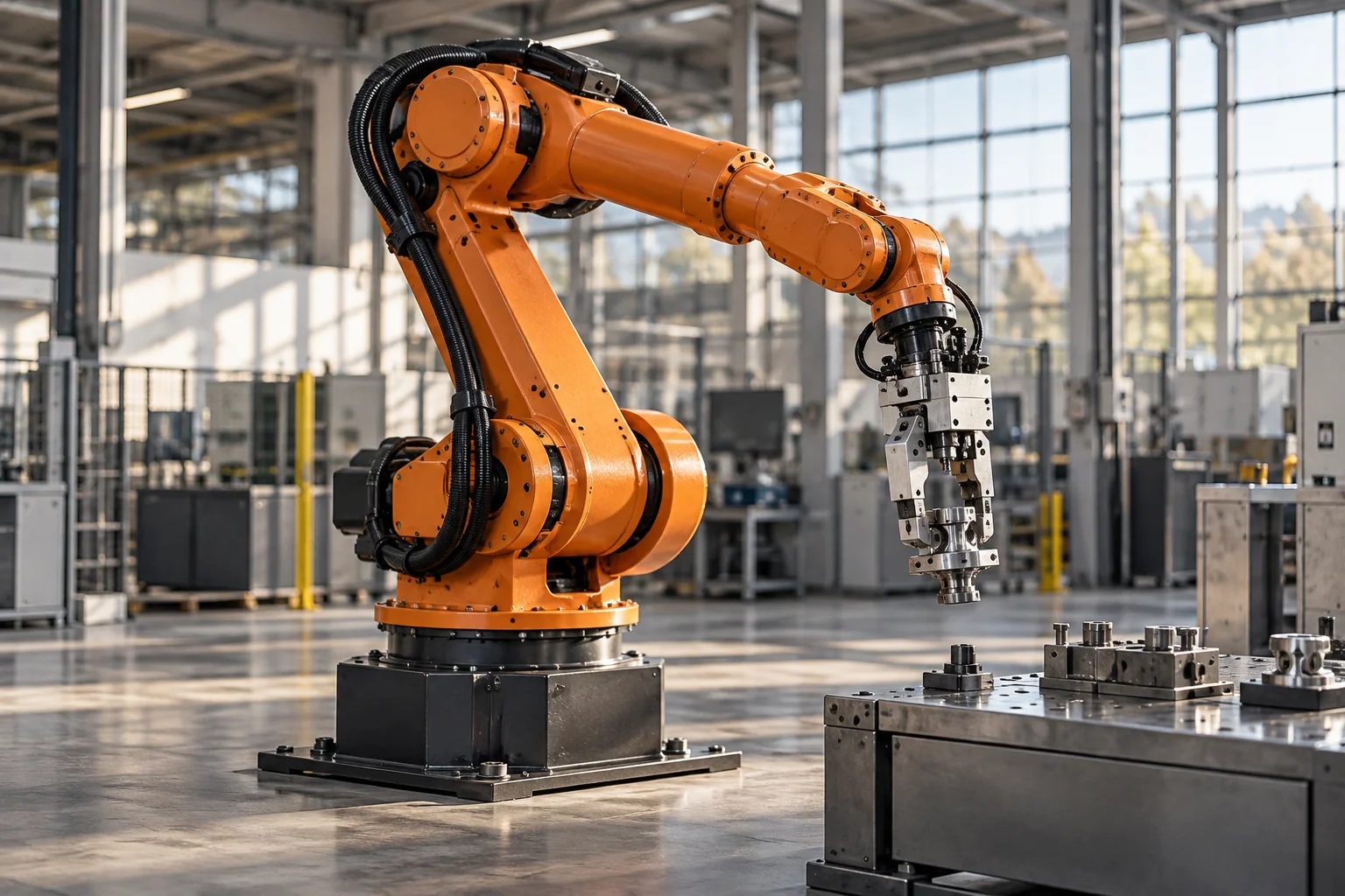
How Does an Industrial Robot Work?
A programmable mechanism needs a task
An industrial robot is a controlled mechanical system that moves a tool, component, or workpiece through a planned sequence. The arm is its most visible part, but the useful machine also includes drives, a controller, an end effector, sensing, and the surrounding production equipment. A robot becomes productive when these elements work together on a defined task, such as handling material, welding, dispensing, or tending another machine.
Not every industrial robot resembles a human arm. Cartesian gantries, parallel robots, SCARA arrangements, and articulated arms use different kinematic structures. Their shapes determine what motions they can perform efficiently. A familiar six axis articulated robot is especially useful for explanation because its joints can position and orient a tool, but it is one architecture among several rather than a universal standard for automation.
Joints transform motor rotation into useful motion
Each powered joint contains an actuator and a mechanical transmission suited to its load and movement. Electric servomotors are common, with reduction mechanisms increasing output torque and controlling motion at the joint. Bearings support the rotating parts, while the links carry loads between joints. Cables and hoses must pass through or around those moving connections without being pulled into incompatible paths.
A joint near the base may carry the mass of several downstream links as well as the payload. A wrist joint faces a different combination of speed, orientation, and inertia. Identical motors at every axis would rarely be an efficient design. Torque requirements change with posture because gravity and leverage change. A robot lifting a load close to its body is mechanically different from the same robot holding that load far away, even if the payload mass remains unchanged.
Geometry connects the tool to joint positions
The controller needs a mathematical relationship between joint angles and the position and orientation of the tool. Forward kinematics calculates the tool pose from the joints. Inverse kinematics asks which joint positions can create a desired pose. There may be more than one solution, and some poses may be unreachable because of geometry or movement limits.
This means a straight tool path is not generally produced by turning every joint at a constant speed. Several joints must accelerate and decelerate together to maintain that path. Certain configurations also make particular directions of tool motion difficult to control, a geometric issue often discussed through singularities. Understanding these relationships explains why a robot's reachable volume is more complicated than a simple sphere drawn around its base. Reaching a point and reaching it with the required tool orientation are different requirements.
Servo control follows the planned trajectory
A motion controller generates a trajectory and coordinates the drives. Feedback devices report joint or motor motion, allowing the system to compare requested behavior with measured behavior. Motor current, velocity, acceleration, and position are related, but none alone describes every force acting on the robot. The controller uses an appropriate model and feedback arrangement to manage these interactions.
The payload matters dynamically as well as statically. A large but light object can have substantial rotational inertia, while a compact heavy object creates another set of demands. Tool cables can also exert forces that vary with posture. Motion performance therefore depends on more than a payload label. The path, orientation, speed changes, tooling, and installation all influence what the mechanism can achieve consistently. Control software extends the ability of the structure; it does not remove structural limits.
The end effector is where the work happens
A gripper, welding torch, spindle, suction tool, or dispensing head connects robot motion to the process. Its geometry establishes the actual working point, often described as the tool center point. If that reference changes, the same programmed arm movement can place the process incorrectly. Tool calibration is therefore part of the geometric chain linking the controller to the real task.
A gripping task adds questions about how the object is located and restrained. The robot must not merely touch an item; it must establish a usable relationship to its mass, shape, and surface. Fingers, vacuum devices, magnetic tools, and compliant mechanisms each solve different problems. A highly repeatable arm cannot compensate for an object that shifts unpredictably inside its gripper. Much of successful robotics lies in designing the interface between the robot and the thing it is supposed to manipulate.
Sensing and the surrounding cell
Production objects do not always arrive in the same position. Vision, force sensing, part detection, and external measuring equipment can provide additional information. A camera may identify a part pose, but the robot still needs a known relationship between camera coordinates, robot coordinates, and the tool. The measurements become useful only when those reference systems agree.
The wider cell also establishes the sequence. Conveyors, fixtures, doors, machines, and other robots exchange states and signals. A robot waiting for a fixture is not necessarily underperforming; it may be correctly respecting a process dependency. Throughput is determined by the complete cycle, including handling, process time, and necessary transitions. Adding speed to one motion may have little effect when another stage dominates the cycle. The cell is an interconnected production system rather than a collection of independent fast mechanisms.
Repeatability, accuracy, and flexibility
Robot specifications often distinguish repeatability from absolute accuracy. Returning consistently to a taught location is not the same as placing a tool exactly at an arbitrary coordinate without correction. Structural deformation, calibration, temperature, and transmission characteristics influence the difference. Some tasks depend mainly on repeatability, while others need additional sensing or process calibration to establish the required absolute relationship.
Flexibility also has limits. A programmable arm can change its path, but a new product may still require different tooling, fixtures, access, and process development. This is why the robot should be understood as an adaptable mechanism rather than a machine that automatically knows how to perform any job. Software provides a language for motion; the physical task determines whether that motion is useful. The most effective installations match the architecture and tooling to the production problem rather than relying on general appearance or axis count.
Why industrial robots matter
Industrial robotics connects mechanical linkages with electrical drives, computation, measurement, and manufacturing knowledge. Its development made it practical to repeat complex movements while changing sequences through programming. Different robot forms evolved because handling small components, carrying large loads, and guiding a tool through confined space are fundamentally different mechanical tasks.
To understand a robot, begin at the workpiece and trace backward. Identify the process, the end effector, the necessary tool path, the joint movements that create it, and the structure supporting those movements. Then trace forward through sensing and feedback to see how the machine knows what happened. This approach turns an impressive moving arm into a set of understandable engineering relationships. It also reveals that the robot's intelligence is distributed across design, control, tooling, and the carefully organized environment in which it works.