
How Hydraulic Turbines Work
Water delivers potential and motion
A hydraulic turbine converts energy carried by water into rotating shaft power. In many hydroelectric installations, a difference in elevation supplies gravitational potential energy. Water flows through controlled passages toward a runner, whose blades or buckets receive force from the moving fluid. The shaft then drives a generator or, in other applications, mechanical equipment. The turbine is the bridge between a water system and a rotating machine.
Two quantities help describe the available resource: flow and head. Flow concerns how much water passes through the system, while head expresses the available energy per unit weight of water, often related to an elevation difference. Neither can be considered alone. A large flow with little head presents a different engineering problem from a small flow descending through a substantial height. Turbine families evolved to serve these differing combinations.
The waterway belongs to the mechanism
Before reaching the runner, water may pass through an intake, gates, conduits, and a penstock. Their dimensions and surface conditions influence friction and other hydraulic losses. The route must carry water while managing pressure and structural loads. Screens and intake arrangements also influence what enters the machine. The visible turbine is consequently only one part of the hydraulic energy path.
After the runner, water returns to a downstream channel or reservoir. The difference between upstream and downstream conditions helps determine the energy available at the turbine. Water levels can change, so the usable conditions may vary even when the machinery remains unchanged. A good explanation therefore follows the complete water route rather than treating the runner as if it operated independently inside an unlimited stream.
Impulse turbines use a directed jet
An impulse turbine converts available pressure energy into a fast jet before the water strikes the runner. The buckets redirect that jet, and the resulting change in momentum produces torque. A Pelton runner is a familiar example, with split shaped buckets that divide and turn the incoming flow. Much of the pressure change occurs in the nozzle rather than across the moving buckets.
This arrangement is associated with particular head and flow conditions, rather than every possible hydroelectric site. Nozzle geometry, bucket shape, jet alignment, and speed must work together. Water leaving a bucket should carry away as little usable energy as practical, but the runner cannot extract energy without allowing the water to depart. Even this apparently direct interaction is an exercise in matching moving geometry with a continuous fluid flow.
Reaction turbines exchange pressure and momentum
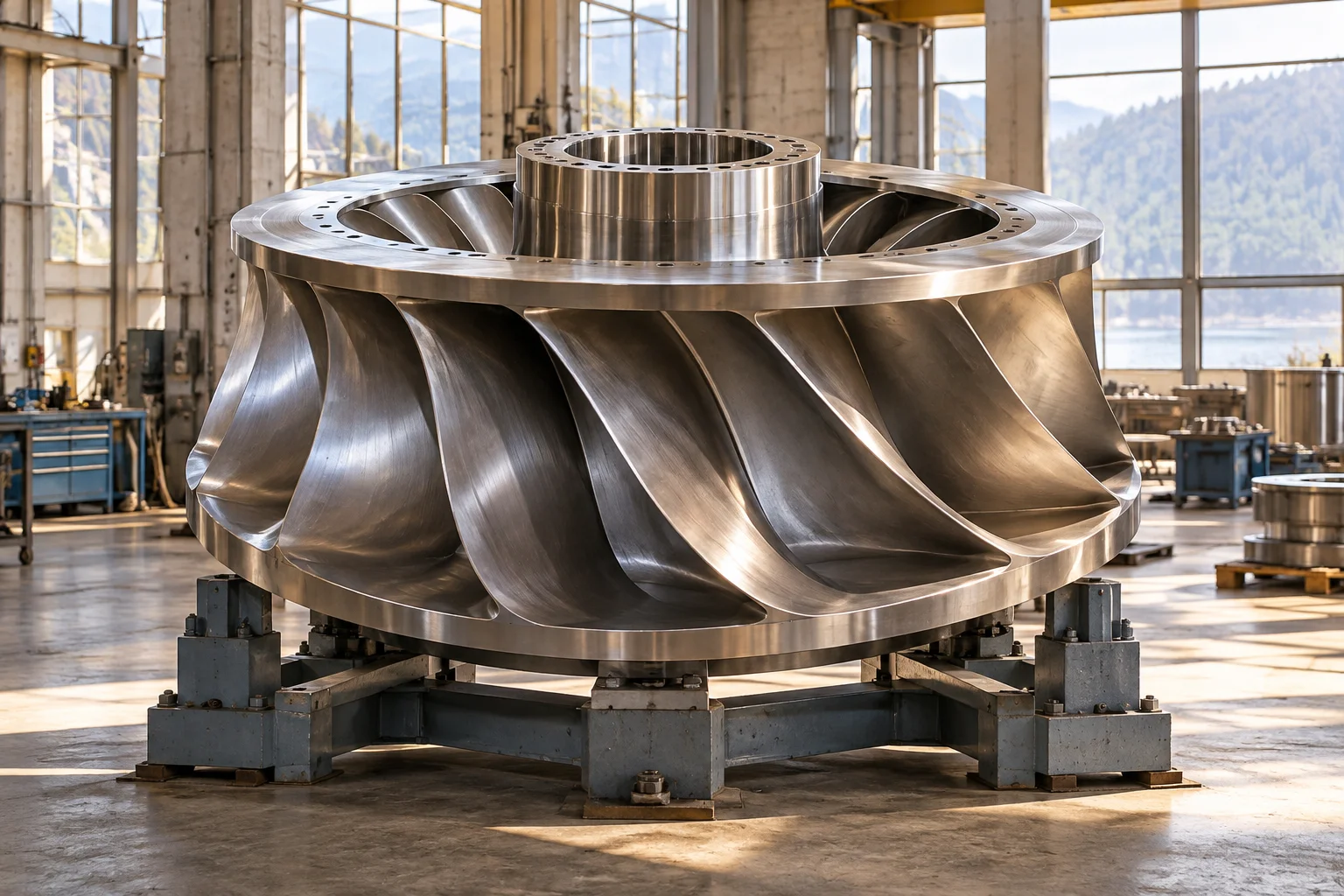
In a reaction turbine, the runner operates within a pressurised water passage, and pressure changes through the runner contribute to energy conversion. Francis turbines guide water inward through a surrounding distribution system and then through the runner. Kaplan type machines use an axial flow arrangement and can include adjustable runner blades. These descriptions identify broad families, with many design variations within them.
Guide vanes help establish the flow entering the runner and can regulate its quantity. In adjustable blade machines, runner blade angle and guide settings may be coordinated to suit changing conditions. The purpose is to maintain useful hydraulic behaviour over the required range. A runner designed for one site cannot simply be scaled or transplanted without considering head, flow, rotational speed, and the conditions at its outlet.
The draft tube completes the flow path
Many reaction turbine installations use a draft tube after the runner. Its expanding passage helps recover some of the outgoing water's kinetic energy as pressure and connects the runner outlet to downstream water. Its shape influences flow separation, vibration, and overall performance. The outlet is therefore an active part of the energy conversion system rather than just a convenient drainage pipe.
Pressure distribution also relates to cavitation, where local conditions allow vapour cavities to form and subsequently collapse. This can affect surfaces, vibration, and efficiency. Runner elevation, geometry, operating condition, and waterway design interact in determining the risk. These relationships illustrate why hydraulic design involves pressures throughout the machine, including regions that are less visually dramatic than the runner inlet.
From runner torque to electrical output
The runner transfers torque through a shaft supported by bearings. Coupling to a generator converts the mechanical output into electricity through electromagnetic induction. Depending on the installation, the shaft may be vertical or horizontal, and thrust bearings support axial loads in addition to rotational components. The surrounding structure must carry the combined mechanical and hydraulic reactions.
Generator speed requirements and turbine hydraulic design influence the final arrangement. Large slow rotating generators can have a very different appearance from machines attached to high speed thermal turbines. Cooling, lubrication, sealing, and access all affect the installation. These supporting systems allow the energy conversion to continue reliably, turning a theoretical water power opportunity into a maintainable generating unit.
Governing a moving column of water
A governor coordinates turbine flow control with the required mechanical output. Adjusting a gate or nozzle changes torque, but the water in a long passage has inertia. Rapid changes can produce pressure transients, so the waterway and control system must be designed together. Surge arrangements and other hydraulic provisions may help accommodate changing conditions, depending on the plant's architecture.
On an electrical network, a generating unit participates in a larger balance of generation and demand. Reservoir conditions, river flow, environmental requirements, and plant constraints also influence its contribution. Hydropower can offer valuable controllability, but that capability belongs to a specific installation with specific water resources. It should not be inferred from the turbine runner alone or confused with an unlimited ability to produce energy at any time.
A family shaped by place
Water powered machines have served mills and workshops for centuries. Modern hydraulic turbines extend that history through fluid mechanics, improved materials, precision manufacturing, and electrical generation. Their diversity reflects the diversity of rivers, reservoirs, and engineering sites. Impulse and reaction machines are different answers to the same underlying question: how can a flowing water resource produce useful torque with acceptable losses and loads?
The broader installation also changes landscapes and water systems, making site selection and environmental design part of its history. Mechanical efficiency does not by itself answer every question about a project. To understand the machine clearly, follow the energy from water elevation and flow through passages, runner, shaft, and generator, while following pressure forces into the structure. This reveals a hydraulic turbine as a carefully matched system whose form is shaped by the place it serves.
Pumped storage illustrates how the same physical relationships can serve another role. Water is raised using electrical energy when the system calls for storage, then released through generating machinery when electricity is needed. Some installations employ reversible pump turbines, while others use separate equipment. The cycle consumes more electrical energy than it returns because every conversion has losses. Its value comes from shifting energy in time and supporting the electricity system, rather than creating an additional energy resource. This application connects turbine design directly with pumping technology, reservoir arrangement, and network operation.