
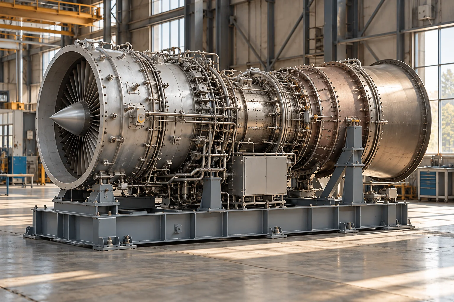
How Gas Turbines Work
Continuous flow produces rotating power
A gas turbine converts the energy of a hot flowing gas into shaft power. Its central elements are a compressor, a combustion system, and a turbine. Air enters continuously, the compressor raises its pressure, fuel adds energy through combustion, and the turbine extracts work as the hot gas expands. Unlike a piston engine with separate strokes inside moving chambers, a gas turbine carries out these processes in different regions of a continuously operating flow path.
The turbine has an important obligation before any useful external output is available: it must drive the compressor. Only the remaining usable shaft power can serve a generator, pump, compressor, propeller, or another load. In an aircraft jet engine, accelerating the exhaust also creates thrust. These related machines share thermodynamic ideas, but the distribution of useful output distinguishes their architectures and their applications.
The compressor builds the pressure field
Large industrial machines commonly employ axial compressors, where air passes through successive rows of rotating and stationary blades. Rotating blades transfer mechanical energy into the air. Stationary passages redirect the flow and help turn velocity into pressure. A centrifugal compressor instead throws air outward through a rotating impeller and collects it through a diffuser. The appropriate design depends on flow, pressure requirements, package size, and manufacturing choices.
Compression consumes considerable power and heats the air. It is not simply a fan placed before a flame. Blade geometry, clearances, speed, and inlet conditions determine how stably and efficiently the compressor works. The compressor and turbine must function together across changing loads. Variable inlet guide vanes and other controls may help manage that relationship. The machine's internal balance explains why a disturbance at one end can affect the entire system.
Combustion adds heat to moving air
Compressed air enters a combustor, where fuel is introduced and burned. The combustor must maintain a stable flame within a fast moving stream while delivering an appropriate temperature distribution to the turbine. Some incoming air participates directly in combustion, while other portions serve mixing, cooling, and dilution functions. The visible flame is only one part of a carefully organised airflow system.
A combustor also has to manage pressure loss, emissions, material temperatures, and changing demand. These requirements can pull in different directions. Improving mixing can influence combustion stability, while reducing peak flame temperatures can affect pollutant formation. Manufacturers use different combustion arrangements and control methods for different fuels and duties. A gas turbine should therefore be understood as a controlled flow machine rather than a chamber in which fuel is merely set alight.
Turbine blades receive the energy
Hot gas passes through stationary nozzles or guide vanes that direct it toward rotating turbine blades. The changing momentum and pressure of the gas exert torque on the rotor. Successive stages extract energy while the gas expands. The shaft carries that torque back to the compressor and onward to the useful load. Shaft bearings and the surrounding casing maintain the required alignment between rotating and stationary parts.
High gas temperature can improve the potential thermodynamic performance, but also challenges materials. Turbine components may use specialised alloys, protective coatings, and internal cooling passages. Cooling air itself has a cost because it comes from the compressed airflow and affects the main gas path. The design is a compromise among temperature, life, efficiency, complexity, and maintainability. The smallest blade is therefore connected to decisions about the performance of the complete power plant.
Shafts and loads shape the architecture
Some machines connect compressor, turbine, and generator through a single principal shaft arrangement. Other designs use a gas generator section and a separate power turbine that delivers external shaft output. Aircraft derived industrial turbines and large purpose designed power turbines may consequently look different even when they use the same broad cycle. Gearboxes can adapt shaft speed to the connected equipment.
The load also matters. An electrical generator connected to a large alternating current network faces different speed and control requirements from a process compressor whose demand changes with a plant. Starting equipment first brings the rotating system into a condition where combustion and turbine output can sustain it. Once running, the control system coordinates fuel and airflow with the demands and limits of the whole assembly.
Recovering energy from the exhaust
The exhaust leaving a simple cycle turbine still contains substantial heat. A heat recovery steam generator can use that heat to produce steam for a steam turbine, creating a combined cycle plant. The gas turbine and steam system then convert different portions of the original fuel energy into electrical output. Heat may also serve industrial processes or district heating in a combined heat and power arrangement.
A recuperator takes a different approach by transferring exhaust heat to the compressed air before combustion. Its usefulness depends on the temperatures, pressure ratio, pressure losses, and practical size of the heat exchanger. These examples demonstrate that turbine efficiency is not just a property of the rotor. The plant around the machine determines how much of the remaining thermal energy is recovered and put to useful work.
Controls follow a changing environment
Air density changes with ambient temperature and pressure. Inlet filtration, duct resistance, and exhaust conditions also influence the flow machine. A turbine that performs well under one set of conditions will not necessarily deliver the same output everywhere. Performance comparisons require a defined basis rather than a single impressive power figure detached from its environment.
Sensors monitor rotation, temperatures, pressures, vibration, and other indicators. Control systems adjust fuel and, where fitted, airflow geometry to coordinate demand with stable operation and component limits. These controls also connect the turbine to electrical or process plant systems. They cannot eliminate the physics of thermal expansion, rotor dynamics, or compressor behaviour; they make those relationships manageable within the intended operating range.
Why this machine changed power engineering
Gas turbines offer concentrated rotating power with a continuous flow architecture. Their development depended on advances in aerodynamics, high temperature materials, precision manufacturing, and combustion research. The same foundation helped transform aviation and contributed a major family of industrial power systems. Modern improvement often happens in details that remain hidden from the outside, including blade cooling, seals, coatings, and control software.
Their strengths and compromises become clear by following the energy. Shaft work first compresses air, fuel raises the flow's thermal energy, expansion returns work to the shaft, and exhaust carries away what remains. An efficient installation coordinates every stage and often recovers additional heat. This makes a gas turbine both a remarkable individual machine and a component whose value depends strongly on the larger system it serves.
Transient behaviour adds another design challenge. Hot casings and rotors do not expand at identical rates, and different components store different amounts of heat. Clearances that work at a steady condition must also remain appropriate during changing conditions. This makes thermal modelling and component construction important companions to aerodynamic design. A turbine's reputation for smooth continuous rotation should not obscure the changing temperatures and internal dimensions that accompany real service. Long term performance depends on managing those relationships throughout the machine's intended duty.