
How Excavators Turn Hydraulic Power into Controlled Digging
A machine built around reach
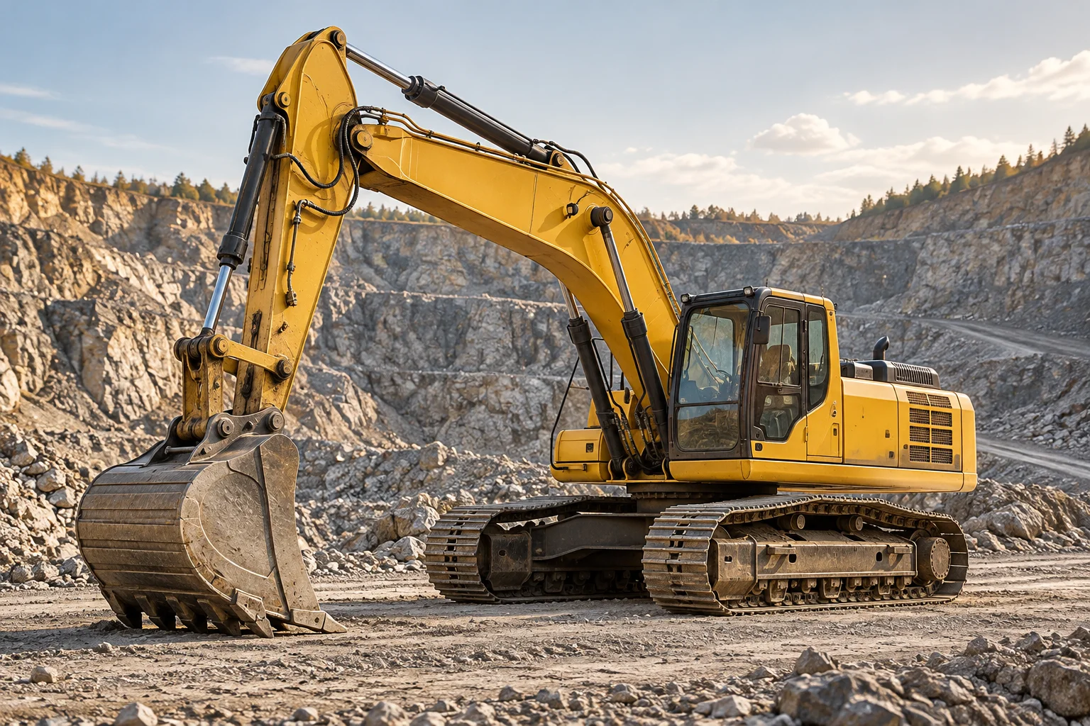
An excavator is a mobile platform for applying force at the end of an articulated arm. Its familiar task is digging, but the same arrangement can lift, sort, break, grade, or handle material when fitted with an appropriate attachment. The essential advantage is separation between the place where the machine stands and the place where its tool works. A tracked excavator can remain on a prepared position while its bucket travels down into a trench, pulls material inward, and swings toward a waiting vehicle. Understanding that separation makes the machine easier to read: the undercarriage supports it, the upper structure turns, and the working equipment reaches into the surrounding space.
Following the energy
A conventional excavator begins with a diesel engine driving hydraulic pumps. Battery electric and other arrangements change the source of power, but they do not remove the need to control force and motion. Pumps move oil; pressure develops as actuators encounter resistance. Valves direct flow toward cylinders or hydraulic motors, while relief and regulating devices manage the circuit. Hydraulic cylinders move the boom, stick, and bucket linkage. Motors usually provide travel and upper structure rotation. The system therefore distributes one power source among several motions that may happen together. Its challenge is not simply producing a large force, but allocating available flow smoothly as the tool meets changing ground resistance.
Reading the arm as a linkage
The boom raises and lowers the outer working assembly. The stick changes the distance between the boom tip and bucket pivot. The bucket curls about its hinge, often through a linkage that changes mechanical advantage throughout the stroke. These movements combine to trace a digging path. Cylinder force alone does not describe force at the teeth: lever arms, joint angles, bucket geometry, and the position of the material all matter. A long reach gives access to distant work but can reduce the force available in a particular configuration. This is why arm geometry is a central design choice rather than an incidental shape surrounding a powerful engine.
The bucket meets the ground
Digging is a material interaction, not an empty movement through space. Teeth initiate penetration, the cutting edge separates material, and the bucket shell gathers it. Loose gravel behaves differently from sticky clay or fractured rock. The tool must overcome cutting resistance while avoiding a path that merely drags soil without filling the bucket. Resistance passes backward through pins, bushings, weldments, the upper frame, and finally into the tracks and ground. Loads can vary suddenly as a tooth encounters a buried obstruction. Structural durability therefore depends on fatigue resistance, joint design, lubrication, and controlled motion as well as on the maximum force advertised for the machine.
Turning without relocating
Between the upper structure and undercarriage sits a large slewing bearing. It carries vertical loads and overturning moments while permitting the house to rotate. A swing drive turns the upper assembly, allowing a digging and dumping cycle without repeatedly moving the tracks. Engine, hydraulic equipment, cab, and counterweight rotate with that upper assembly. The counterweight contributes to balance, but it does not make every reach or suspended load acceptable. Geometry and orientation affect how forces are supported. The rotary connection also has to accommodate services between stationary and rotating parts, so hydraulic passages and electrical arrangements become part of the design that makes continuous turning practical.
Tracks, ground pressure, and support
The undercarriage converts driving torque into movement through sprockets and track chains. Rollers support the machine as the track circulates, and shoes spread the load over the surface. Wide contact can help on soft ground, yet actual support depends on soil conditions and load distribution rather than on an average pressure alone. Tracks also produce traction through interaction with the ground, not through friction in a simple laboratory model. Wheeled excavators trade some of this arrangement for road mobility and different support systems. Compact machines, long undercarriages, and specialist low ground pressure versions show how the same digging concept changes when access, transport, or soil bearing becomes the limiting requirement.
A working cycle and its limits
A typical cycle brings the tool into position, penetrates the material, fills the bucket, raises it clear, swings to a discharge point, empties it, and returns. Some motions overlap, so good hydraulic coordination can matter as much as peak speed. The machine must accelerate and decelerate a substantial moving mass, including material whose weight and distribution vary. Every abrupt change asks the structure and control system to handle additional dynamic forces. An excavator used for demolition or lifting may follow a very different cycle from one digging loose soil. Equipment configuration and application therefore determine useful performance; there is no single productivity figure that describes the entire machine family.
Controls, attachments, and precision
The operator's controls request movements that hydraulic and electronic systems translate into actuator commands. Modern assistance can help guide the tool toward a reference surface or coordinate an attachment, but sensors do not make the machine independent of its physical limitations. Position, angle, pressure, and speed information must be interpreted through a model of the equipment. Attachments also impose different requirements: a breaker needs an appropriate hydraulic supply, a grapple needs controlled opening and rotation, and a grading bucket changes the relationship between edge position and ground shape. The excavator is consequently best understood as a configurable mechanical platform whose versatility depends on compatible tools and well controlled power.
From cable shovels to hydraulic platforms
Earlier powered excavators often used drums, ropes, and relatively rigid structural arrangements to control digging tools. Hydraulic systems made it practical to place compact actuators directly between moving members, producing the articulated machines now common on construction sites. The change was more than replacing a cable with a cylinder. It altered packaging, control, attachment flexibility, and the range of movements available from one position. Current development continues along those lines through electrification, improved hydraulic efficiency, remote operation, and better sensing. The enduring engineering question remains the same: how can a mobile machine place a useful tool accurately while reacting the resulting forces safely into the ground?
Why coordination matters
Consider an arm movement that brings a bucket along a level line. Moving only the boom generally produces an arc, and moving only the stick produces another arc. A nearly straight tool path requires the joints to work together. The hydraulic system must also respond when the bucket suddenly fills, because the load has changed while the desired path may not have. This is a useful distinction between force capability and control quality. An excavator can be powerful yet difficult to position accurately if its motions do not combine predictably. Conversely, a well coordinated machine can perform delicate placement as well as heavy digging. Tool position, orientation, and applied force are related but separate quantities, and successful excavation depends on managing all three throughout the cycle.