
How Aircraft Work
Supporting weight without a road
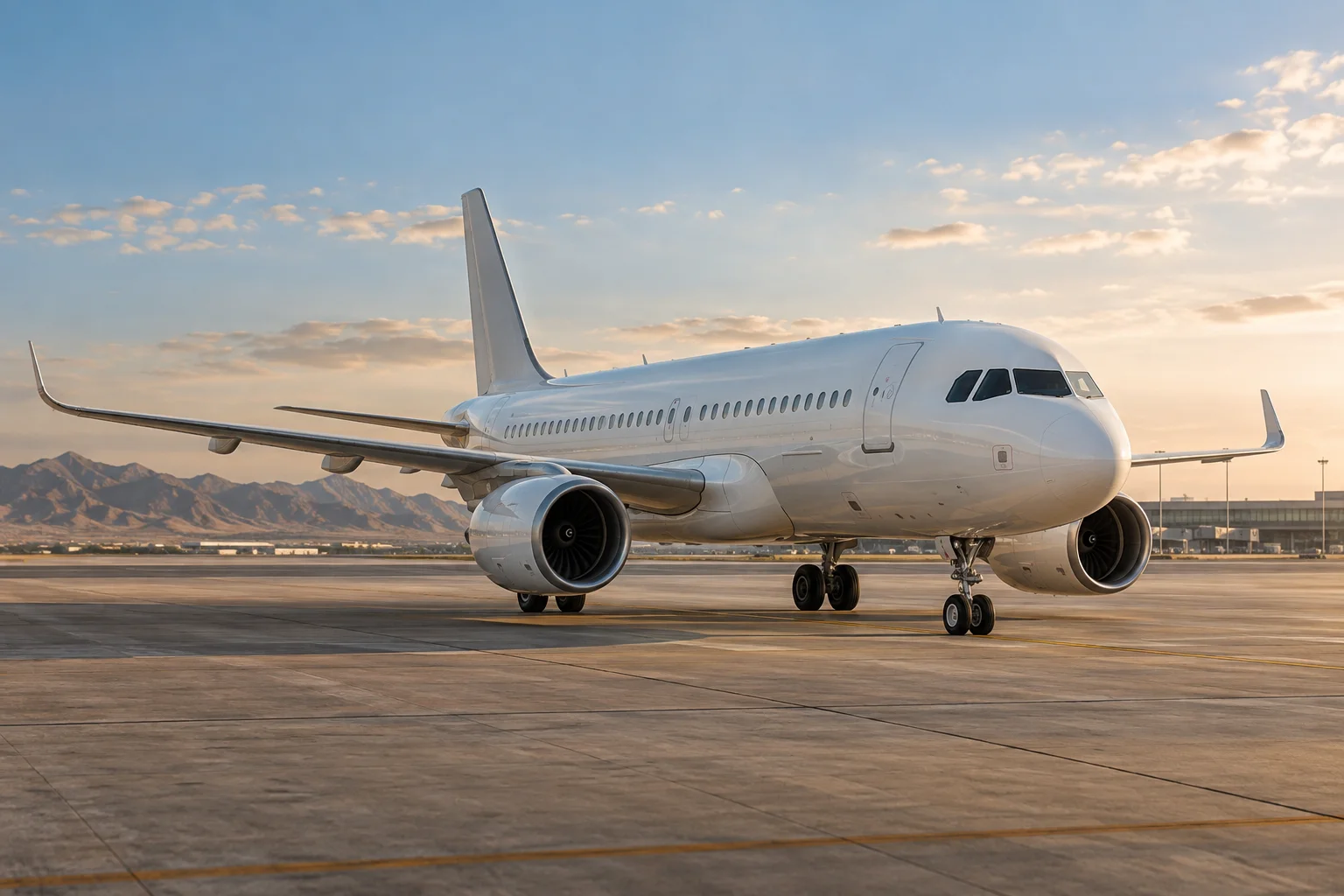
An aircraft must create forces that support and control it while moving through air. This introduction focuses on powered fixed wing aircraft, while recognizing that helicopters, gliders, and other machines solve the same broad transport problem differently. Wings generate most of the supporting aerodynamic force; propulsion supplies thrust; the structure carries loads; control surfaces manage orientation and flight path. The complete vehicle also needs landing gear, fuel or electrical storage, instruments, and supporting systems. Its engineering is unusually sensitive to mass because every additional component must itself be carried through flight. Useful payload therefore competes directly with structure, energy storage, equipment, and the margins needed for the intended mission.
Airflow creates a pressure distribution
A wing interacts with moving air through its shape, orientation, and surface condition. Pressure varies around it, and the integrated aerodynamic force has lift and drag components. The airflow also changes direction and momentum, connecting the pressure explanation to the larger movement of air around the aircraft. Lift does not require air particles passing above and below a wing to meet again at the trailing edge. That familiar shortcut gives the wrong physical picture. The amount of lift depends on air density, relative speed, wing area, and the aerodynamic characteristics associated with shape and angle of attack. The wing and the surrounding flow must be considered together.
Four forces describe different flight conditions
Weight acts toward Earth, lift acts perpendicular to the relative airflow, drag opposes that airflow, and thrust follows the propulsion system's effective direction. In steady straight level flight, their components balance. During a climb, descent, acceleration, or turn, the balance changes. A banking aircraft tilts its lift vector, providing the sideways force needed to curve its flight path while also affecting the vertical component. This is why simply equating lift with weight does not describe every maneuver. The aircraft's response depends on forces and moments together: the location of each force relative to the center of gravity determines how it tends to rotate the machine.
Wings balance efficiency and practical structure
Long slender wings can reduce the induced drag associated with producing lift, but greater span also creates structural and packaging challenges. Wing sweep, thickness, area, and internal arrangement reflect the intended speed and mission. Spars and ribs carry loads through the wing, while the outer skin contributes to the structure in many designs. Fuel may occupy internal wing space, adding another changing load. Flaps and other high lift devices alter aerodynamic behavior for slower phases of flight, accepting additional drag and mechanical complexity. A wing optimized for efficient cruising is consequently part of a compromise that must also accommodate takeoff, landing, structural strength, fuel storage, and manufacturing.
Propellers and jets both accelerate air
A propeller uses rotating blades to accelerate air rearward, producing forward thrust through reaction. Its shaft may be driven by a piston engine, turbine, or electric motor. A gas turbine engine compresses incoming air, adds heat through combustion, and extracts energy through turbines. In a turbofan, a large fan contributes substantially to thrust, with air passing around the core as well as through it. These arrangements suit different combinations of speed, size, efficiency, and installation needs. Thrust is not created by pushing against a solid surface behind the aircraft. It results from the interaction between the propulsion system and the flow of air moving through and around it.
Control surfaces manage rotational moments
An aircraft rotates in pitch, roll, and yaw about its center of gravity. Elevators or other pitch control arrangements influence nose attitude, ailerons commonly create rolling moments, and the rudder influences yaw. Their effects interact, so coordinated control involves more than assigning one surface to one isolated motion. Some aircraft transmit pilot input through cables and linkages; others use hydraulic assistance or electrical flight control commands. Stability describes how the aircraft responds to disturbances, while control authority describes its ability to change state deliberately. Designers balance these qualities with maneuverability, efficiency, and the intended operating envelope. Tail surfaces, wing placement, and mass distribution all participate in that balance.
Structure must survive repeated changing loads
An aircraft structure experiences lift distributed across the wings, concentrated masses from engines and equipment, cabin loads, landing forces, and aerodynamic pressures. A pressurized fuselage also undergoes repeated pressure cycles as flights begin and end. Engineers must consider fatigue and damage tolerance as well as the maximum load in a single event. Metals and composites offer different combinations of strength, stiffness, mass, manufacturing methods, and inspection requirements. Joints, openings, and abrupt changes in geometry deserve particular attention because they can concentrate stress. The lightest possible individual component is not necessarily the best solution if it complicates attachments, maintenance, or the load paths of the complete airframe.
Landing gear works during brief demanding phases
Landing gear supports the aircraft on the ground and absorbs energy when it returns to a runway. Wheels, tires, struts, brakes, and their attachments must carry loads under conditions very different from steady flight. Shock absorbing struts manage vertical movement, while wheel brakes dissipate energy during the ground roll. Retractable gear reduces aerodynamic drag during flight but adds actuators, doors, locks, structure, and monitoring. Fixed gear can offer simplicity for aircraft whose missions do not justify that complexity. The landing gear demonstrates a recurring aircraft tradeoff: equipment needed for a relatively short part of the mission can impose mass and packaging costs throughout the entire flight.
A flight links several energy problems
Takeoff requires acceleration and sufficient aerodynamic capability at relatively low speed. Climb increases potential energy, cruise continually overcomes drag, and descent releases stored height while managing speed and configuration. Fuel burned during the journey reduces mass and can change balance, while electrical loads and environmental systems add continuing power demands. High altitude conditions affect both the atmosphere surrounding the aircraft and the systems supporting people inside it. The best engine or wing considered alone cannot determine mission efficiency. Route length, payload, reserves, weather, ground operations, and the time spent in each flight phase shape the result. Aircraft are designed around these complete mission profiles rather than one attractive peak performance number.
Experiment, integration, and continuing development
Powered flight emerged from the convergence of aerodynamic knowledge, lightweight structures, engines, propellers, and effective control. Improvements in any one field became useful only when the complete aircraft could exploit them. That pattern continues in modern developments involving materials, electrical propulsion, automated assistance, and new configurations. A new energy source still has to support adequate range, thermal management, structural integration, and reliable control. The historical lesson is therefore one of systems engineering: flight became practical when supporting weight, producing thrust, maintaining balance, and controlling motion were solved together. Following those connections makes aircraft understandable as machines, while also explaining why apparently small changes can have consequences throughout the vehicle.