
How Does a 3D Printer Work?
Geometry is built rather than merely revealed
A 3D printer turns a digital description of an object into a physical part by adding material in a controlled sequence. This differs from removing material from a solid blank and from forcing material into a complete mould. The printer must establish not only the outside shape but also how each new region connects to material already deposited or formed.
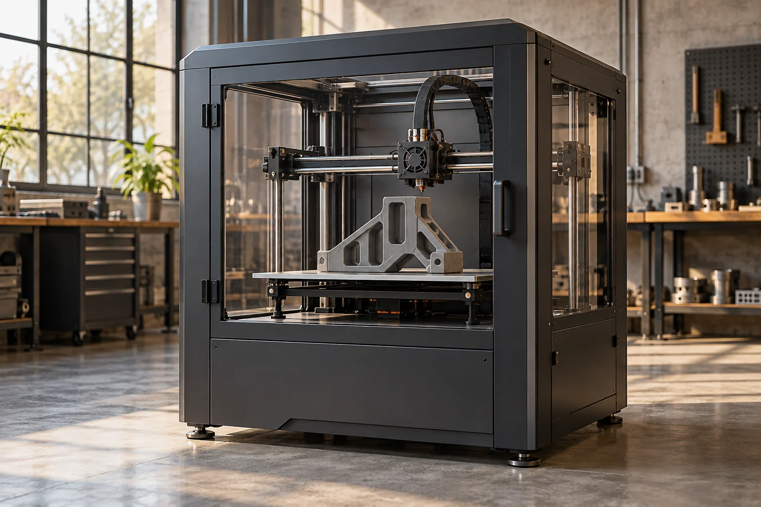
The term includes several very different technologies. Material extrusion, powder bed processes, vat photopolymerization, and directed energy deposition do not share one universal working mechanism. The enclosed machine commonly seen in workshops may use material extrusion, where a feedstock passes through a nozzle and is placed along a path. That process provides a useful introduction, provided its features are not incorrectly presented as rules for every form of additive manufacturing.
A digital model becomes a manufacturing plan
A model describes desired geometry, but a printer needs an ordered set of process actions. Preparation software divides or otherwise organizes the shape into layers and generates paths, exposures, or other machine instructions. Layer thickness, internal structure, support geometry, and the relationship between adjacent paths affect the resulting part. These are manufacturing decisions rather than merely display preferences.
A model that looks complete on a screen may contain regions that cannot be built in the chosen orientation without extra support. Reorientation can change surface quality, build time, support requirements, and mechanical behavior. The digital preparation stage therefore connects geometry to the physical characteristics of a particular process. It is not simply a neutral conversion from a picture to motion. The software must express a plausible sequence of material transformations that a real machine can carry out.
Material extrusion coordinates feeding, heat, and movement
In a common filament process, a drive pushes material toward a heated extrusion zone. The material softens and is directed through a nozzle, which deposits it along the programmed route. Motion systems position the nozzle relative to the build surface. Some machines move the head in several directions; others divide movement between the head and the platform.
The amount delivered must agree with the space being filled and the relative speed of travel. A change in motion can alter the required feed, while pressure and material behavior mean the output may not respond instantly to a command. The nozzle's geometry and thermal condition influence the deposited path. What appears to be a thin thread is actually the product of interacting feeding, heating, flow, and motion systems. Consistent results require their coordinated behavior rather than perfect positioning alone.
Each layer changes the conditions for the next
New material arrives on a surface created by earlier process steps. Its temperature, shape, adhesion, and structural support affect the next stage. Cooling can cause contraction, while uneven thermal conditions can create distortion. The build surface must establish a useful initial relationship, but later layers depend increasingly on the behavior of the developing part itself.
Material deposited in one direction can also interact differently with loads than material connecting between layers. This is one reason printed parts cannot always be treated as homogeneous versions of the same material made by another process. Internal path arrangement, voids, orientation, and thermal history can influence their properties. The point is not that additive parts are inherently weak or strong. Their behavior depends on how the process created the structure, so design and manufacture must be considered together.
Supports, overhangs, and internal geometry
A printer cannot assume that every new feature has material directly beneath it. Support structures, bridging behavior, process media, or other methods provide ways to create difficult regions. The available solutions depend strongly on technology. A powder bed can support a developing part differently from a free extrusion process, while metal processes may need supports partly for thermal and distortion control.
Internal geometry is similarly constrained by access and removal. A channel that can be represented digitally is not automatically easy to build, clean, or inspect. The ability to form complicated shapes is valuable, but it does not suspend manufacturing logic. Designers must consider how unwanted material or support will leave the part and how the final object will be verified. Additive manufacturing changes the set of practical possibilities; it does not make every possible model equally useful to manufacture.
Other processes change the central mechanism
In vat photopolymerization, selected regions of a liquid resin are solidified through a controlled light based process. In powder bed systems, a new layer of powder is spread and selected regions are joined through an appropriate energy source or binder related method. Directed energy deposition brings feedstock and energy to a localized working region. Each architecture has its own routes for supplying material, controlling energy, and positioning the process.
These differences affect suitable materials, feature sizes, surface conditions, build rates, and supporting equipment. Calling all these machines printers can make them sound more similar than they are. A useful comparison asks what changes material from its supplied state into a connected part, how that change is localized, and how the next layer or region is established. Those questions reveal more than comparing only the appearance of the machine enclosure or the complexity of its control screen.
The finished build is not always the finished component
Once the main build sequence ends, a part may need cooling, removal from its platform, support removal, cleaning, curing, heat treatment, machining, or other finishing. The necessary steps depend on the process and intended use. Dimensional inspection and material evaluation may also be important where a part must meet a defined engineering requirement.
This wider sequence matters when comparing additive and conventional production. A machine that creates a complex shape in one build has not necessarily completed every required operation. Conversely, combining features can eliminate assembly or tooling steps elsewhere. The appropriate unit of comparison is the complete route to a usable component. Build time, material utilization, geometry, finishing effort, and inspection must be considered together rather than treating the time displayed by the printer as the entire manufacturing story.
Why additive manufacturing changes design choices
The development of 3D printing made it practical to connect digital geometry to physical objects through a range of additive processes. Its value can include rapid design iteration, low volume production, customized geometry, or shapes difficult to make by other routes. The best applications exploit a specific advantage rather than using additive manufacturing simply because the resulting form looks complicated.
A clear explanation follows the information and material together. Trace the model into a process plan, the feedstock into a localized transformation, and the repeated transformations into a connected object. Then continue through finishing and inspection. That view makes the printer recognizable as a manufacturing system with physical limits and distinctive opportunities. The remarkable feature is not that matter appears from nothing, but that geometry can be constructed through many small, coordinated acts of material placement or consolidation.
Material history matters after printing as well. A polymer component may absorb moisture, relax internal stresses, or change dimensions with temperature. A metal component may require heat treatment to establish suitable properties. These effects make the printed shape an intermediate result in some applications. Qualification must connect geometry, material condition, and the actual service environment of the finished object.