
Take a counterbalanced forklift apart and follow the forks, mast, hydraulics, steering, and counterweight through one complete handling cycle.
Take the truck apart
A forklift approaches a pallet, slides its forks underneath, raises the load, and carries it away. The movement looks simple. Making it happen takes several systems working together.
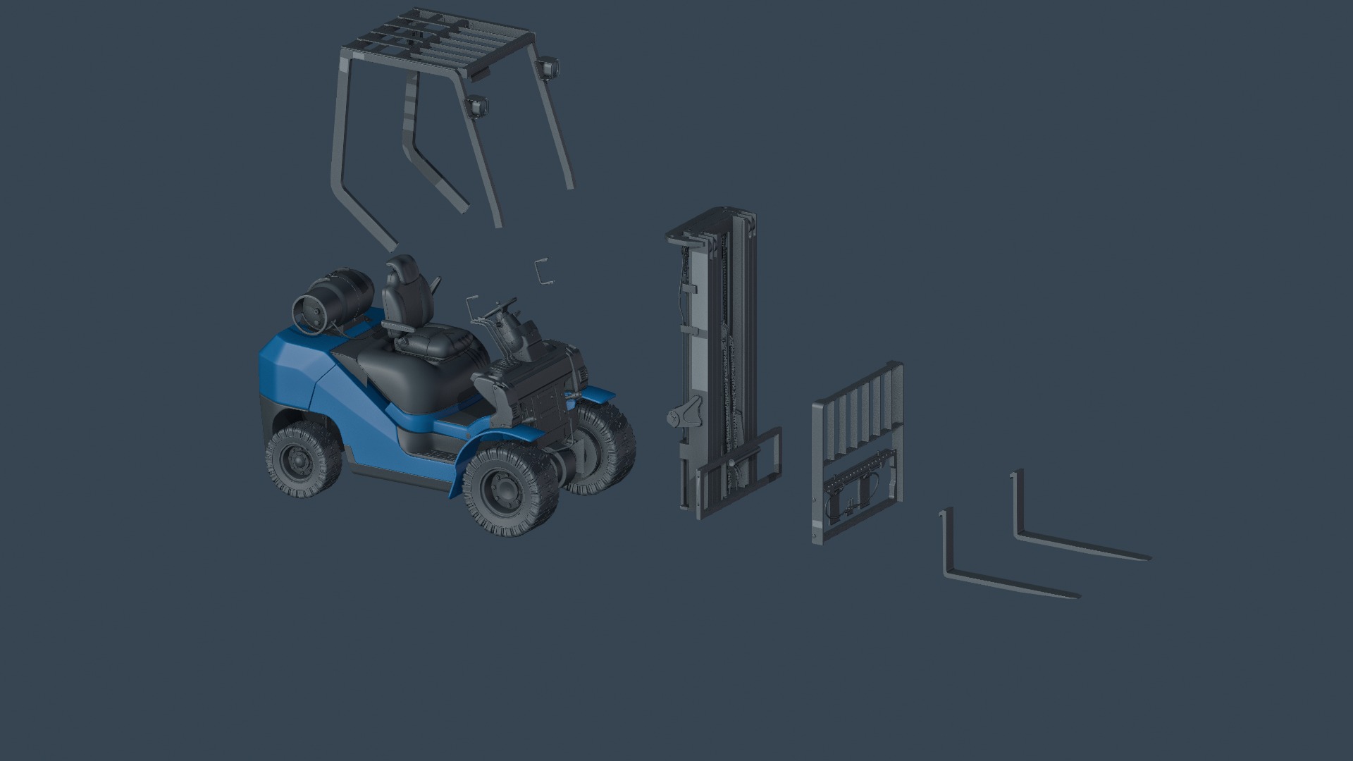
Figure 1 · The major assemblies separated: truck body, overhead guard, mast, carriage, and two forks.
Our example is a counterbalanced forklift. At the front, two forks support the load. They attach to a carriage that travels along the mast. The body contains the power and control systems, while the wheels move and steer the truck. The truck’s own weight, including its rear counterweight, helps balance the load in front.
Each assembly has a distinct job: the forks meet the load, the carriage connects it to the lifting mechanism, the mast guides its movement, and the hydraulics supply lifting force.
Why are the forks L-shaped?
Each fork has a horizontal blade and an upright section. The blade slides underneath the pallet and supports its weight. The upright section attaches to the carriage, transferring the load into the lifting assembly.
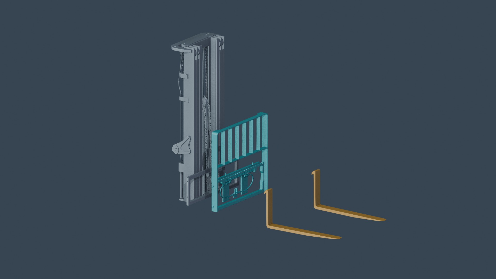
Figure 2 · The horizontal blades support the pallet. The upright sections attach to the carriage; the load backrest extends above it.
The spacing between the forks can be adjusted to suit different pallets and loads. The forks normally support a load from below rather than squeezing it from the sides like a clamp.
Behind them, the carriage provides the mounting and load-bearing connection. Above it, the load backrest helps prevent material from falling backward toward the operator. When the load rises, the forks and carriage move together along the mast.
The mast guides. The chain transfers motion.
The load needs a controlled path as well as an upward force. The mast provides that path, with rollers helping the carriage travel along its rails.
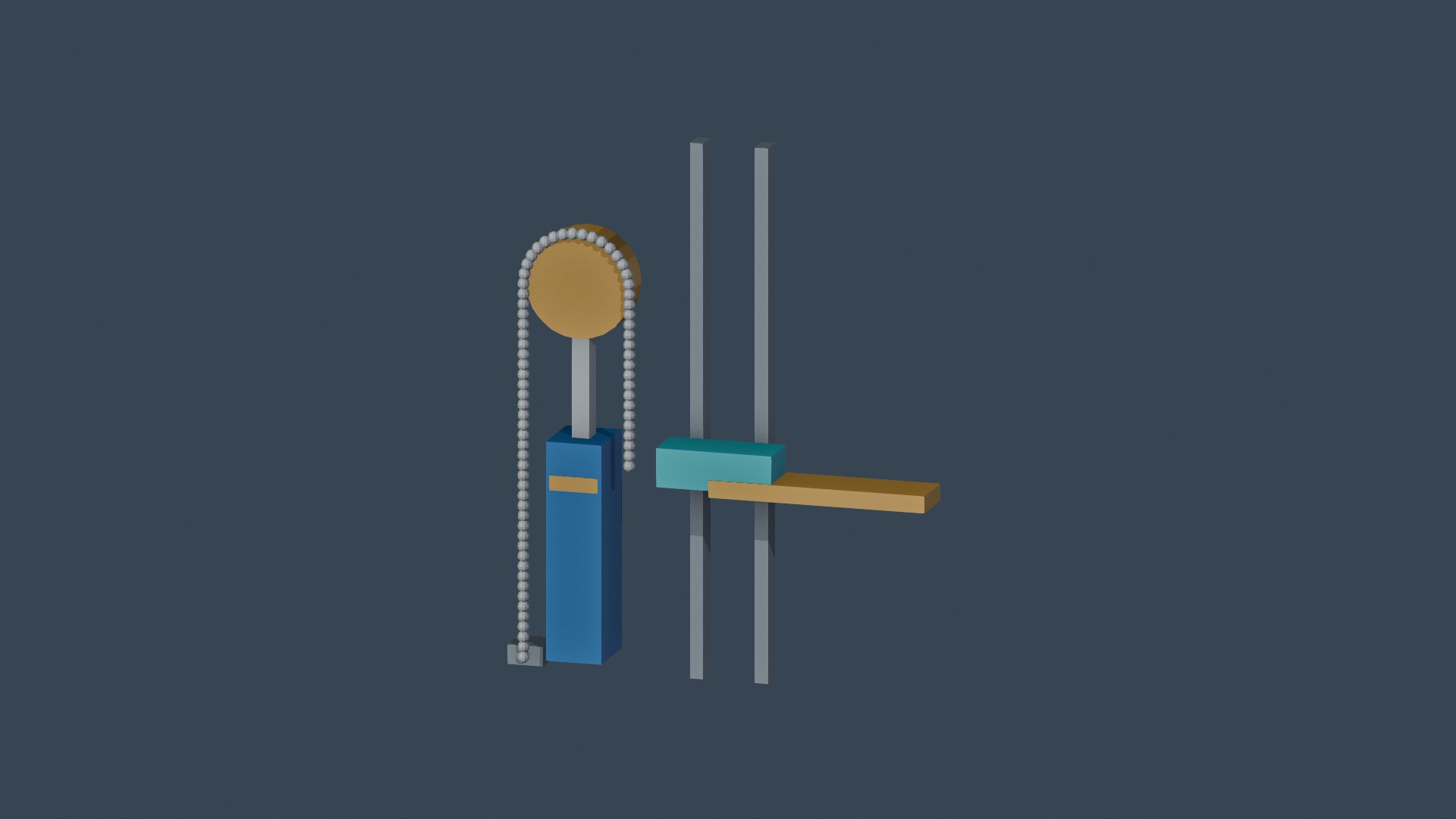
Figure 3 · A separate simplified mechanism shows the cylinder raising a chain pulley and the chain lifting the carriage.
In one common lifting arrangement, a hydraulic cylinder raises a chain pulley, and the chain lifts the carriage. The video separates this mechanism from the truck so the relationship is easier to see: the carriage can travel approximately twice as far as the moving pulley.
That is an increase in travel, not free energy. Different mast designs use different stages, cylinder positions, and chain arrangements. This diagram explains a common principle; it is not a reconstruction of every forklift’s internal mechanism.
Hydraulics turn fluid pressure into lifting force
The power source drives a hydraulic pump. The pump moves oil through the system, and pressure develops against the resistance of the load. A control valve determines where the oil flows.
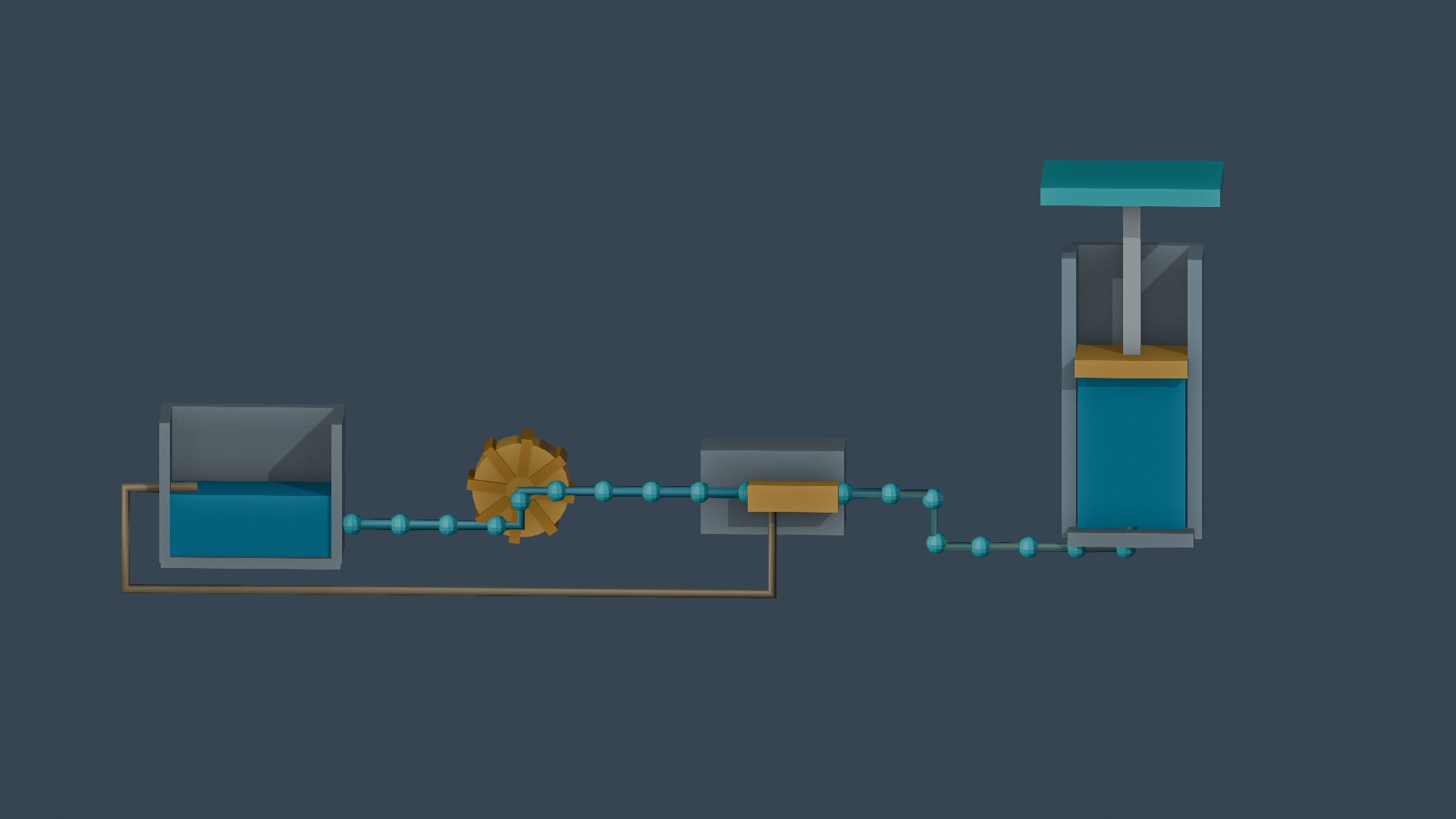
Figure 4 · From left to right: tank, pump, control valve, and lift cylinder. Blue fluid and moving markers illustrate the oil paths.
When the valve directs oil into the lift cylinder, the oil acts on the piston and extends the piston rod. The cylinder converts hydraulic pressure into mechanical force, which the lifting mechanism transfers to the forks and their load.
To lower the load, the valve allows oil to return to the tank at a controlled rate. As oil leaves the cylinder, the load descends. The mast guides the movement while the hydraulic system supplies and controls the lifting action. Real circuits contain additional valves and protective features beyond this simplified diagram.
Watch the rear wheels—and the tail
Many counterbalanced forklifts drive through their front wheels and steer with their rear wheels. This helps the operator position the forks in confined working spaces.
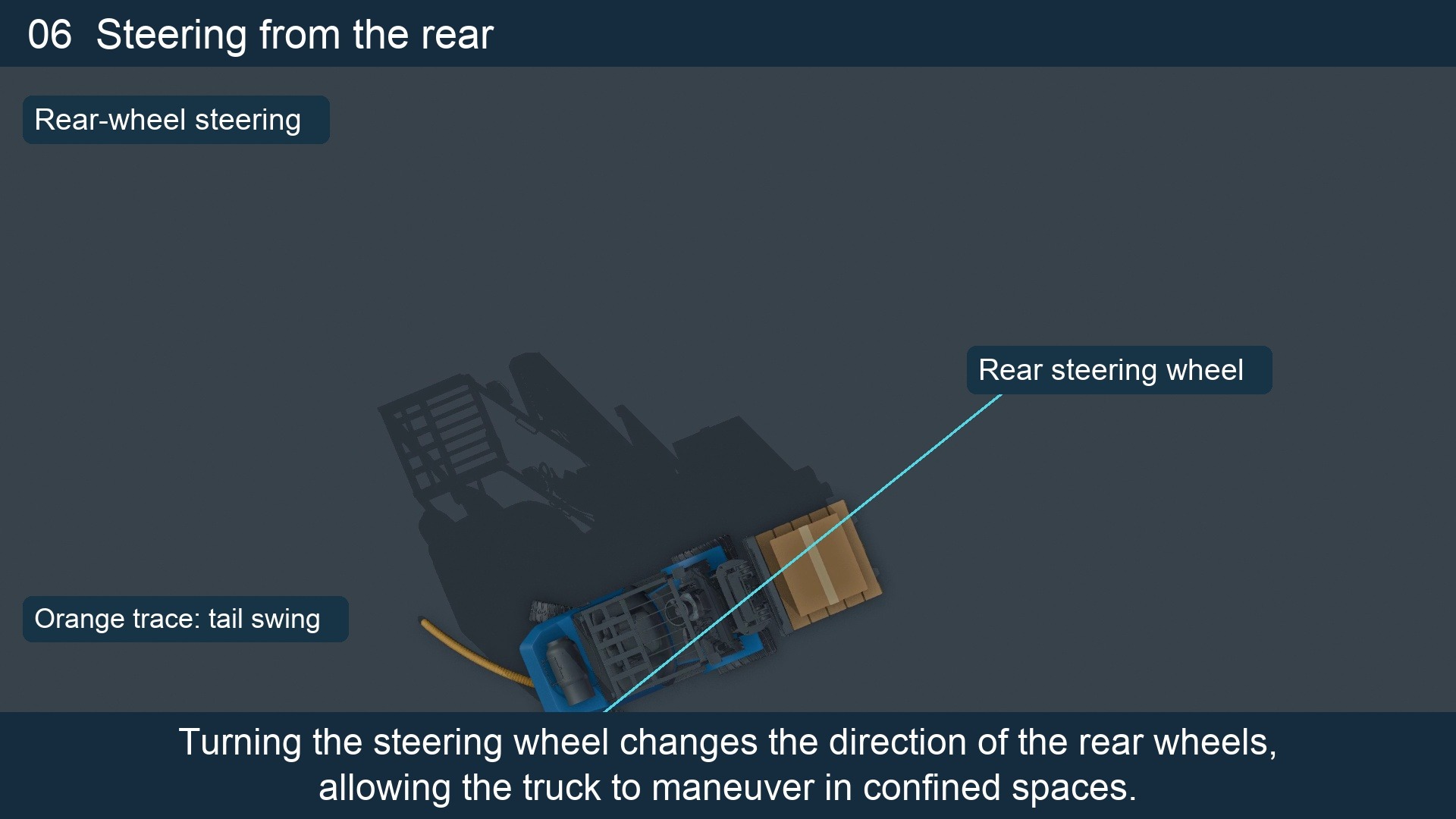
Figure 5 · An overhead view of rear-wheel steering. The orange trace helps reveal the area swept by the back of the truck.
But rear-wheel steering creates an easily overlooked movement: the tail swings outward during a turn. Seeing that the forks clear an obstacle does not tell you whether the back of the truck will clear it too.
The overhead shot makes that relationship visible. Following the rear of the truck is more revealing than watching the steering wheel alone.
Why doesn’t the load tip the truck forward?
Viewed from the side, the front wheel support line provides a useful reference for understanding forward tipping. The load creates a tipping moment on one side, while the truck’s own weight, including its rear counterweight, acts in the opposite direction.
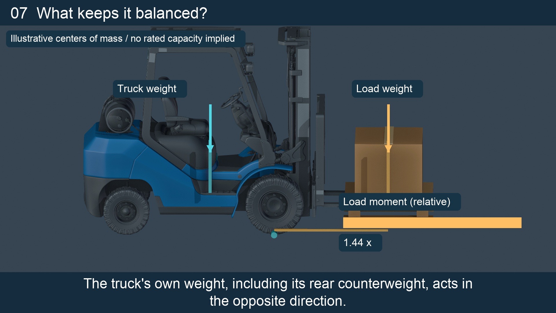
Figure 6 · A simplified side-view balance diagram. Moving the load forward increases its relative tipping moment; the displayed value is not a lifting-capacity rating.
Distance matters as well as weight. Move the same load farther forward and the horizontal distance from its center of gravity to the tipping reference increases. Its tipping moment increases too: with the weight unchanged, increasing that distance by half increases the moment by half.
This is a simplified explanation of longitudinal static balance. Actual stability also depends on factors such as center-of-gravity position, lift height, turning, and motion. A side-view diagram alone cannot establish that a truck is stable in use. Rated capacity must be understood from the truck’s data plate and the specified conditions, rather than guessed from its size. [1]
One handling cycle brings the systems together
Return to the apparently simple job at the start. The operator aligns the truck with the pallet and inserts the forks. Hydraulic power lifts the load clear of the floor. The wheels move the truck, and the steering system helps position it at the destination.
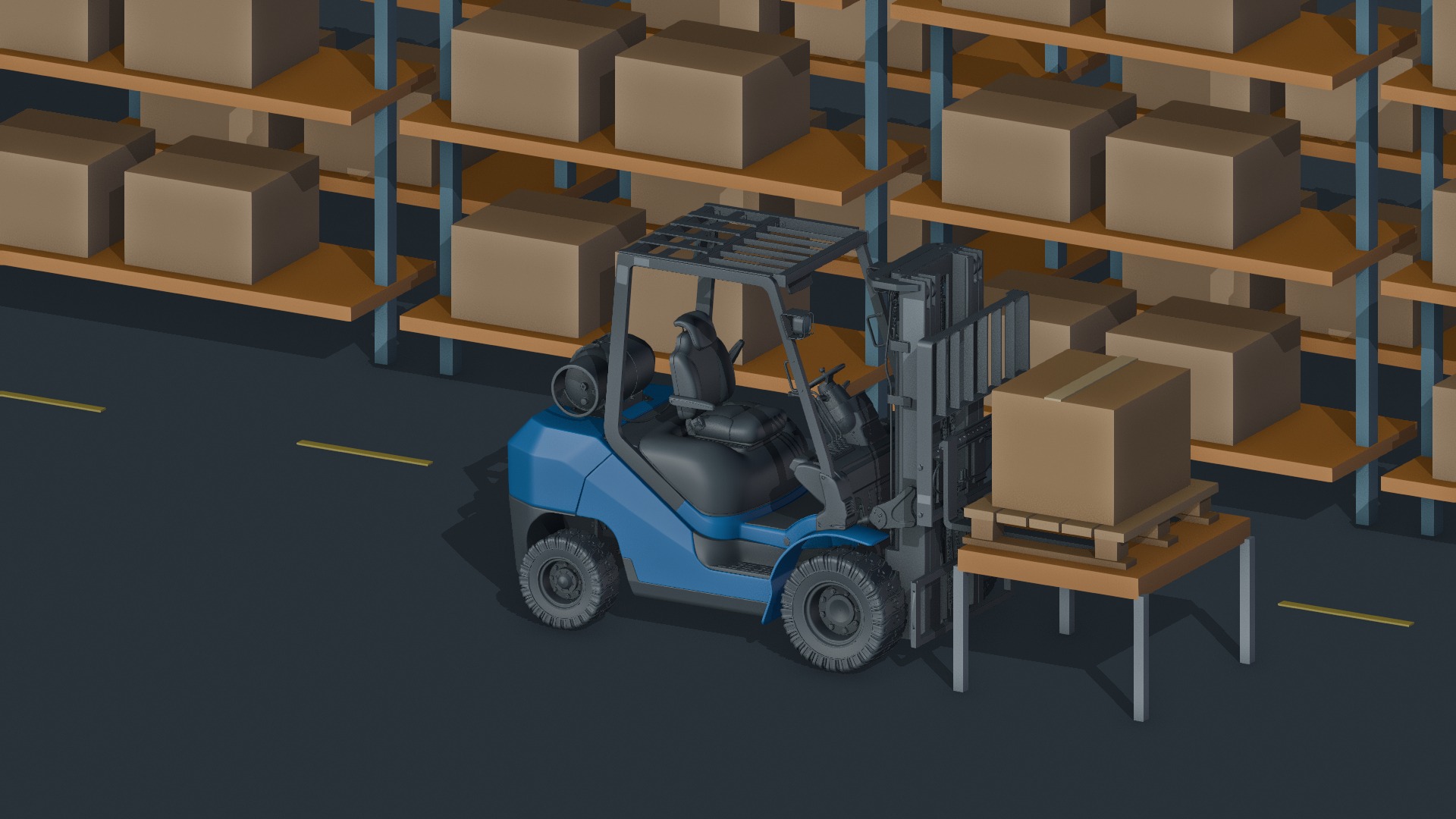
Figure 7 · At the destination, the load is lowered onto its support before the forks withdraw.
At the rack, the lifting mechanism raises the load to the required height. The truck positions it over the support, lowers it until the support carries its weight, and then withdraws the forks. The animation keeps these stages separate so their relationship is clear.
The next time you see a forklift working, follow the sequence: how the forks support the pallet, how the carriage travels along the mast, how the hydraulics produce movement, how the tail swings, and how the truck balances the load. A single handling cycle reveals several mechanical systems acting together.
Images come from the video’s 3D scenes or finished frames. The chain, hydraulic, and balance diagrams are simplified teaching models, not a reconstruction of the C01 truck’s original internal systems. This article is a mechanical explainer, not an operator-training guide.
Adapted from How Does a Forklift Work? | 3D Breakdown of Hydraulics, Steering & Balance, Mechanica Planet.
[1] Stability and load-position reference: OSHA, Load Composition and Stability of Powered Industrial Trucks.
Forklift exterior asset: NVIDIA, PhysicalAI-SimReady-Warehouse-01 / SM_Forklift_C01_Blue_01, used under CC BY 4.0. Adaptations include material preparation, component grouping, and animation. All article images are project renders or video frames; no additional third-party live-action photographs are included.
Mechanica Planet · October 27, 2026
COMMENTS (0)
Please Login to join the discussion.